|
|
|
PDF U6084B-FP Data sheet ( Hoja de datos )
| Número de pieza | U6084B-FP | |
| Descripción | PWM Power Control with Automatic Duty-cycle Reduction | |
| Fabricantes | ATMEL Corporation | |
| Logotipo | ||
Hay una vista previa y un enlace de descarga de U6084B-FP (archivo pdf) en la parte inferior de esta página. Total 10 Páginas | ||
|
No Preview Available !
Features
• Pulse-width Modulation up to 2 kHz Clock Frequency
• Protection against Short-circuit, Load-dump Overvoltage and Reverse VS
• Duty-cycle 0 to 100% Continuously
• Output Stage for Power MOSFET
• Interference and Damage Protection According to VDE 0839 and ISO/TR 7637/1
• Charge-pump Noise Suppressed
• Ground-wire Breakage Protection
Description
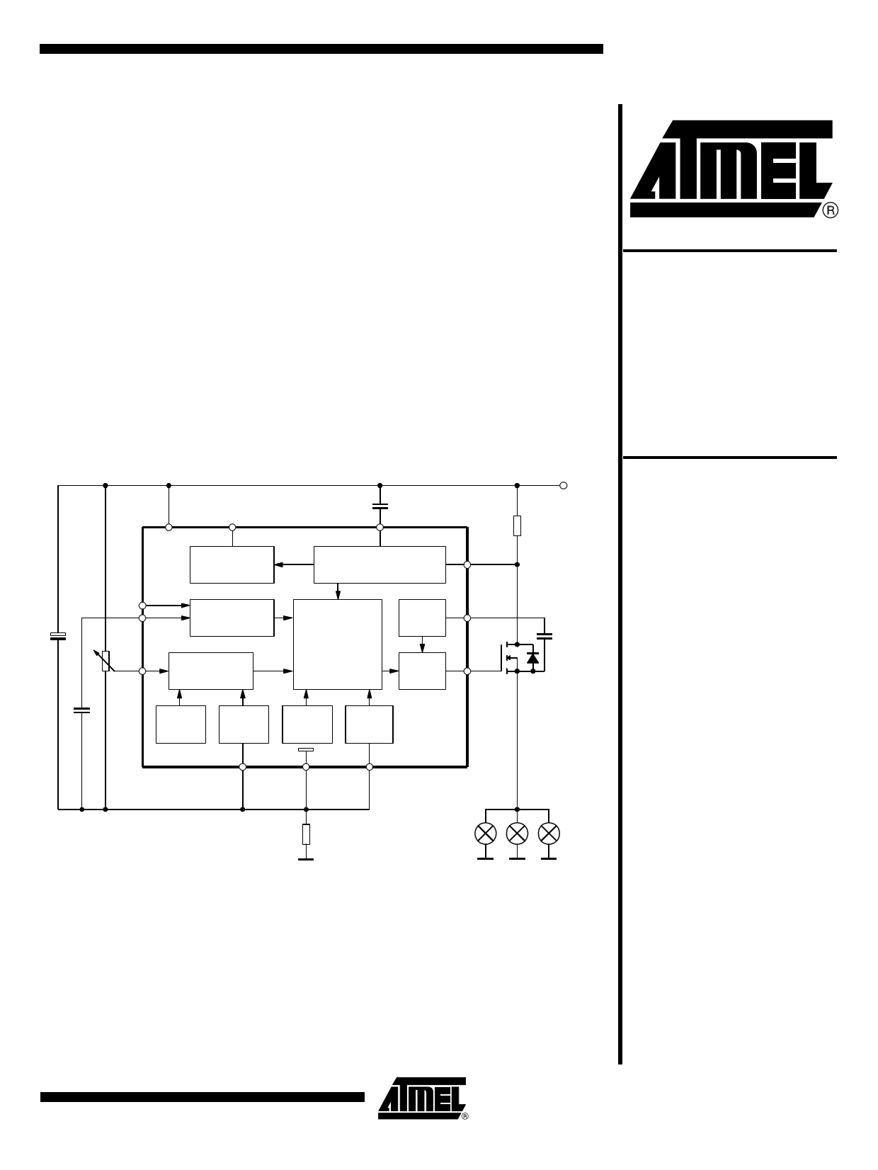
The U6084B is a PWM-IC with bipolar technology designed for the control of an
N-channel power MOSFET used as a high-side switch. The IC is ideal for use in the
brightness control (dimming) of lamps such as in dashboard applications. For constant
brightness, the preselected duty-cycle can be reduced automatically as a function of
the supply voltage.
Figure 1. Block Diagram with External Circuit
VS
16
9
Short circuit
latch monitoring
5
6
C1 47 kΩ
RC oscillator
Control input
3
C5
11
Current monitoring
+ short circuit detection
12
PWM
Logic
Charge 13
pump
14
Output
C2
Duty cycle
range
0-100%
Duty cycle
reduction
Voltage
monitoring
Enable/
disable
4 12
Rsh
VBatt
C3
47 nF
PWM Power
Control with
Automatic
Duty-cycle
Reduction
U6084B
150 Ω
R3
Ground
Rev. 4677B–AUTO–02/04
1 page 
U6084B
Pins 11 and 12 – Short-circuit Protection and Current Sensing
Short-circuit Detection and
Time Delay td
The lamp current is monitored by means of an external shunt resistor. If the lamp current
exceeds the threshold for the short-circuit detection circuit (VT2 ≈ 90 mV), the duty cycle
is switched over to 100% and capacitor C5 is charged by a current source of 20 µA
(Ich - Idis). The external FET is switched off after the cut-off threshold (VT11) is reached.
Renewed switching on the FET is possible only after a power-on reset. The current
source, Idis, ensures that capacitor C5 is not charged by parasitic currents. Capacitor C5
is discharged by Idis to typ. 0.7 V.
Time delay, td, is as follows:
td = C5 × -(--V--(--1I--c-1-h---–--–--0--I--.d-7--i-s--V)-----)
With C5 = 330 nF and VBatt = 12 V, we have
td = 330 nF × -(--9---.--8----2-V--0---–---µ--0-A--.--7-----V-----) = 150 ms
Current Limitation
The lamp current is limited by a control amplifier that protects the external power transis-
tor. The voltage drop across an external shunt resistor acts as the measured variable.
Current limitation takes place for a voltage drop of VT1 ≈ 100 mV. Owing to the differ-
ence VT - VT2 ≈ 10 mV, current limitation occurs only when the short-circuit detection
circuit has responded.
After a power-on reset, the output is inactive for half an oscillator cycle. During this time,
the supply voltage capacitor can be charged so that current limitation is guaranteed in
the event of a short-circuit when the IC is switched on for the first time.
Pins 13 and 14 – Charge
Pump and Output
Pin 14 (output) is suitable for controlling a power MOSFET. During the active integration
phase, the supply current of the operational amplifier is mainly supplied by capacitor C3
(bootstrapping). Additionally, a trickle charge is generated by an integrated oscillator
(f13 ≈ 400 kHz) and a voltage doubler circuit. This permits a gate voltage supply at a
duty cycle of 100%.
Pin 16 – Supply Voltage,
Vs or VBatt
Undervoltage Detection
In the event of voltages of approximately VBatt < 5.0 V, the external FET is switched off
and the latch for short-circuit detection is reset.
A hysteresis ensures that the FET is switched on again at approximately VBatt ≥ 5.4 V.
Overvoltage Detection
Stage 1
Stage 2
If overvoltages of VBatt > 20 V (typically) occur, the external transistor is switched off and
switched on again at VBatt < 18.5 V (hysteresis).
If VBatt > 28.5 V (typically), the voltage limitation of the IC is reduced from 26 V to 20 V.
The gate of the external transistor remains at the potential of the IC ground, thus pro-
ducing voltage sharing between the FET and lamps in the event of overvoltage pulses
(e.g., load-dump). The short-circuit protection is not in operation. At VBatt < 23 V, the
overvoltage detection stage 2 is switched off.
4677B–AUTO–02/04
5
5 Page | ||
| Páginas | Total 10 Páginas | |
| PDF Descargar | [ Datasheet U6084B-FP.PDF ] | |
Hoja de datos destacado
| Número de pieza | Descripción | Fabricantes |
| U6084B-FP | PWM Power Control with Automatic Duty-cycle Reduction | ATMEL Corporation |
| U6084B-FP | PWM Power Control with Automatic Duty Cycle Reduction | TEMIC Semiconductors |
| Número de pieza | Descripción | Fabricantes |
| SLA6805M | High Voltage 3 phase Motor Driver IC. |
Sanken |
| SDC1742 | 12- and 14-Bit Hybrid Synchro / Resolver-to-Digital Converters. |
Analog Devices |
|
DataSheet.es es una pagina web que funciona como un repositorio de manuales o hoja de datos de muchos de los productos más populares, |
| DataSheet.es | 2020 | Privacy Policy | Contacto | Buscar |