|
|
|
PDF ACT2813C Data sheet ( Hoja de datos )
| Número de pieza | ACT2813C | |
| Descripción | 5V/2.4A Power Bank Solution | |
| Fabricantes | Active-Semi | |
| Logotipo | ||
Hay una vista previa y un enlace de descarga de ACT2813C (archivo pdf) en la parte inferior de esta página. Total 23 Páginas | ||
|
No Preview Available !
ACT2813/ACT2813C
FEATURES
• Dedicated Single Chip Solution for Mobile Power
With Minimal Component Count
• 2.4A Continuous Output Current in Boost Mode
• 2.4A Switching Charger Current
• 96% Boost Efficiency (Vbat=4.1V)
• Adaptive to 10mA-2400mA Input Sources
• Battery Disconnection at Output Short
• <10µA Low Battery Leakage Current at HZ
Mode During Storage
• Boost Auto Turn-off at No Load and Push
Button Turn-on
• Battery Over Current, Over Voltage, Over
Temperature and Short Circuit Protections
• Boost Auto Startup with Load Detection
• Prioritized Power Path from Input to Output
• 5V+/-100mV Output Voltage in Boost Mode
• 1.1MHz/0.55MHz Switching Frequencies
• 2.2uH Inductor and Low Profile Ceramic
Capacitor
• 4 LEDs Battery Level and Status Indication
• Battery Impedance Compensation
• Full Cycle of Battery Charge Management
Preconditioning, Fast Charge, Top off and End
of Charge
• Charge Current Foldback at 110°C Die
Temperature
• IC Over Temperature Protection at 160°C
• FCQFN 4x4-20 Package
Rev 2, 19-May-15
5V/2.4A Power Bank Solution
APPLICATIONS
• Power Bank
• Mobile Power
• Backup Battery Pack
• Standalone Battery Charger with USB Output
GENERAL DESCRIPTION
ACT2813/ACT2813C is a space-saving and high-
performance low-profile single-chip solution for
backup battery pack and standalone battery
charger. ACT2813/ACT2813C integrates all the
functions that a backup battery pack needs,
including switching charger, boost converter and
LED indication.
ACT2813/ACT2813C operates at 1.1MHz for
switching charger and 0.55MHz for boost converter
allowing tiny external inductor and capacitors.
ACT2813/ACT2813C provides a direct power path
from input to output while providing power to
switching charger. Output has higher priority than
battery charger if the input current limit is reached.
ACT2813/ACT2813C charges battery with full cycle
of preconditioning, fast charge with constant current
and constant voltage until end of charge. The
battery charger is thermally regulated at 110°C with
charge current foldback.
ACT2813/ACT2813C boost converter steps battery
voltage up to 5V. Boost converter features high
efficiency, constant current regulation, short circuit
protection and over voltage protection.
ACT2813/ACT2813C provides 3.5mA constant
currents to drive 4 LEDs to indicate battery level
and charge status. Battery impedance is
compensated for battery level indication.
Innovative PowerTM
-1-
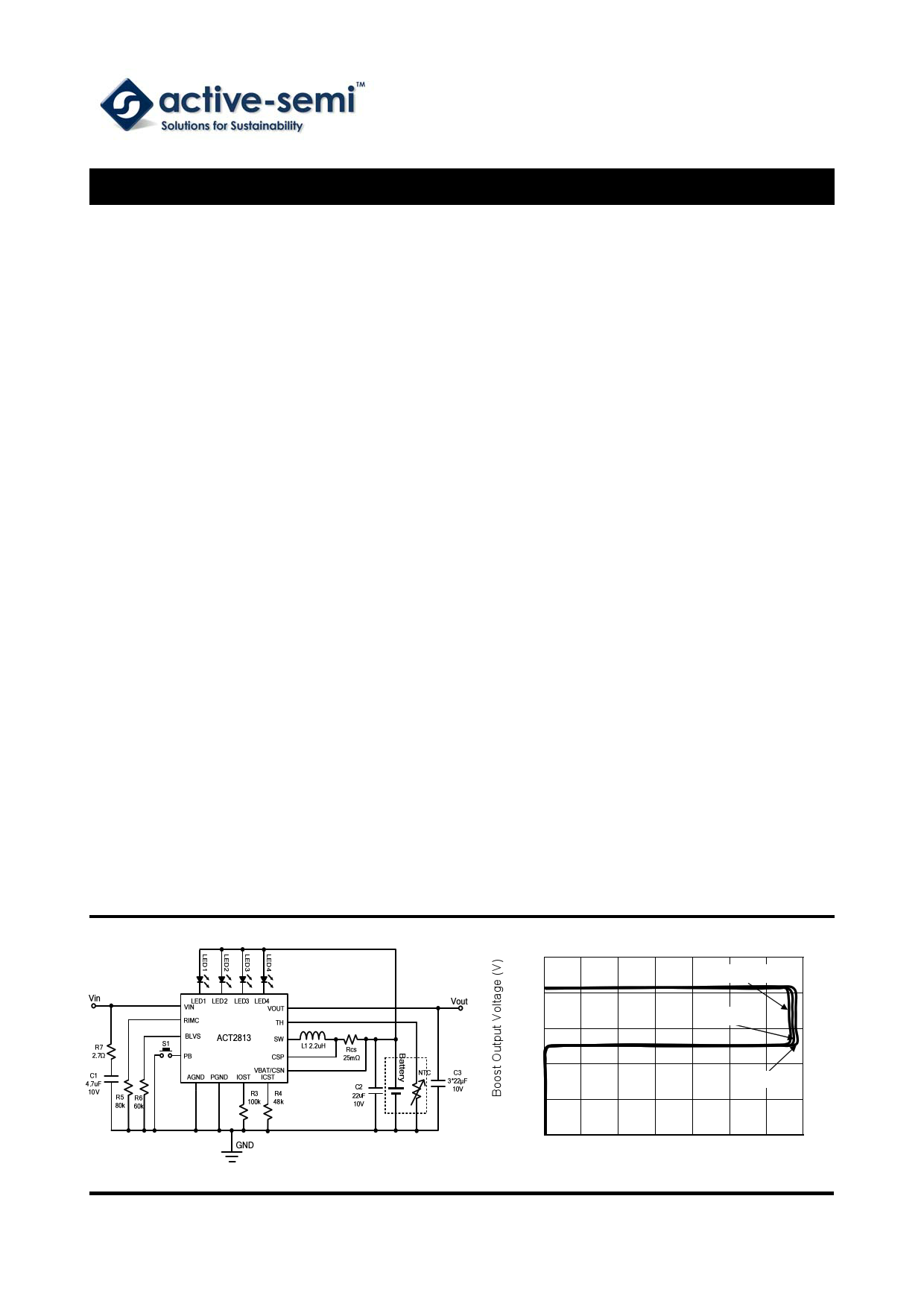
Boost CC/CV Profile
5.5
VBAT =3.2V
5.0
VBAT =3.7V
4.5
4.0
VBAT =4.1V
3.5
3.0
0
0.4 0.8 1.2 1.6 2.0 2.4 2.8
Output Current (A)
www.active-semi.com
Copyright © 2015 Active-Semi, Inc.
1 page 
ACT2813/ACT2813C
Rev 2, 19-May-15
ELECTRICAL CHARACTERISTICS
(VIN = 5V, TA = 25°C, unless otherwise specified.)
PARAMETER
TEST CONDITIONS
Input Current Limit
Input Voltage Range
VIN Over Voltage Protection
VIN rising, VIN_OVP
Input Voltage Validation Time
VIN_UVLO<VIN<VIN_OVP
Leakage Current from VOUT to VIN in Boost
Mode
3.0V<VBAT<4.2V, Ta=25℃
Battery Discharge Current in High-Z Mode 3.0V<VBAT<4.2V, Ta=25℃
Power Switches
VIN-to-VOUT FET on Resistance
VOUT-to-SW FET on Resistance
SW-to-PGND FET on Resistance
Buck Converter
Switching Frequency
High Side Switch Peak Current Limit
Minimum On-time
Over Temperature Protection (OTP)
OTP rising
OTP Hysteresis
OTP falling
Charge Mode
Charge Current Setting Range
Charge Current Setting (ICHRG)
Thermal Regulation Temperature
Rcs=25mΩ, RICST=20kΩ—60kΩ
Rcs=25mΩ, RICST=48kΩ
End of Charge (EOC) Voltage
ACT2813/ACT2813C
ACT2813-T0435/ACT2813C-T0435
Battery Over Voltage Threshold
VBAT rising
Battery Over Voltage Threshold Hysteresis VBAT falling
Fast Charge Current
VBAT=3.5V
Precondition Charge Current
2.4V≤VBAT≤2.8V, Percent of ICHRG
Precondition Voltage Threshold
VBAT rising
Precondition Voltage Threshold Hysteresis
MIN
4.5
5.5
-15%
4.5
1.0
-10%
-0.5%
-0.5%
TYP
6.0
32
0
7.5
60
45
45
1.1
6
100
160
35
2.4
110
4.2
4.35
4.6
200
ICHRG
10
2.8
130
MAX
UNI
T
5.5 V
6.5 V
ms
10 µA
15 µA
mΩ
mΩ
mΩ
+15% MHz
A
ns
℃
℃
3.0 A
+10% A
+0.5%
℃
V
+0.5% V
V
mV
A
%
V
mV
Innovative PowerTM
- 5 - www.active-semi.com
Copyright © 2015 Active-Semi, Inc.
5 Page 
ACT2813/ACT2813C
Rev 2, 19-May-15
Recharge
When battery voltage drops by 200mV below the end of charge voltage, the charger is reinitiated with con-
stant current charge.
Figure 3.
Typical Li+ Charge Profile and ACT2813/ACT2813C Charge States
A: PRECONDITION STATE
B: FAST-CHARGE STATE
C: TOP-OFF STATE
D: END-OF-CHARGE STATE
Figure 4.
Charger State Diagram
Innovative PowerTM
- 11 -
www.active-semi.com
Copyright © 2015 Active-Semi, Inc.
11 Page | ||
| Páginas | Total 23 Páginas | |
| PDF Descargar | [ Datasheet ACT2813C.PDF ] | |
Hoja de datos destacado
| Número de pieza | Descripción | Fabricantes |
| ACT2813 | 5V/2.4A Power Bank Solution | Active-Semi |
| ACT2813C | 5V/2.4A Power Bank Solution | Active-Semi |
| Número de pieza | Descripción | Fabricantes |
| SLA6805M | High Voltage 3 phase Motor Driver IC. |
Sanken |
| SDC1742 | 12- and 14-Bit Hybrid Synchro / Resolver-to-Digital Converters. |
Analog Devices |
|
DataSheet.es es una pagina web que funciona como un repositorio de manuales o hoja de datos de muchos de los productos más populares, |
| DataSheet.es | 2020 | Privacy Policy | Contacto | Buscar |