|
|
|
PDF RFFC2071 Data sheet ( Hoja de datos )
| Número de pieza | RFFC2071 | |
| Descripción | 2.7GHz RF SYNTHESIZER/VCO | |
| Fabricantes | RF Micro Devices | |
| Logotipo | ||
Hay una vista previa y un enlace de descarga de RFFC2071 (archivo pdf) en la parte inferior de esta página. Total 23 Páginas | ||
|
No Preview Available !
RFFC2071
RFFC2071/2072
2.7GHz RF SYNTHESIZER/VCO WITH
INTEGRATED RF MIXER
Package: QFN, 32-Pin, 5mm x 5mm
RFFC2072
Features
85MHz to 2700MHz LO
Frequency Range
Fractional-N Synthesizer with
Very Low Spurious Levels
Typical Step Size 1.5Hz
Fully Integrated Low Phase Noise
VCO and LO Buffers
Integrated Phase Noise
0.18°rms at 1GHz
High Linearity RF Mixer(s)
30MHz to 2700MHz Mixer
Frequency Range
Input IP3 +23dBm
Mixer Bias Adjustable for Low
Power Operation
Full Duplex Mode (RFFC2071)
2.7V to 3.3V Power Supply
Low Current Consumption
3- or 4-Wire Serial Interface
Applications
CATV Head-Ends
Digital TV Repeaters
Multi-Dwelling Units
Diversity Receivers
Software Defined Radios
Frequency Band Shifters
Point-to-Point Radios
Cellular Repeaters
WiMax/LTE Infrastructure
Cellular Jammers
Satellite Communications
VHF/UHF Radios
Phase
det.
Synth
Ref.
divider
Phase
det.
Synth
Ref.
divider
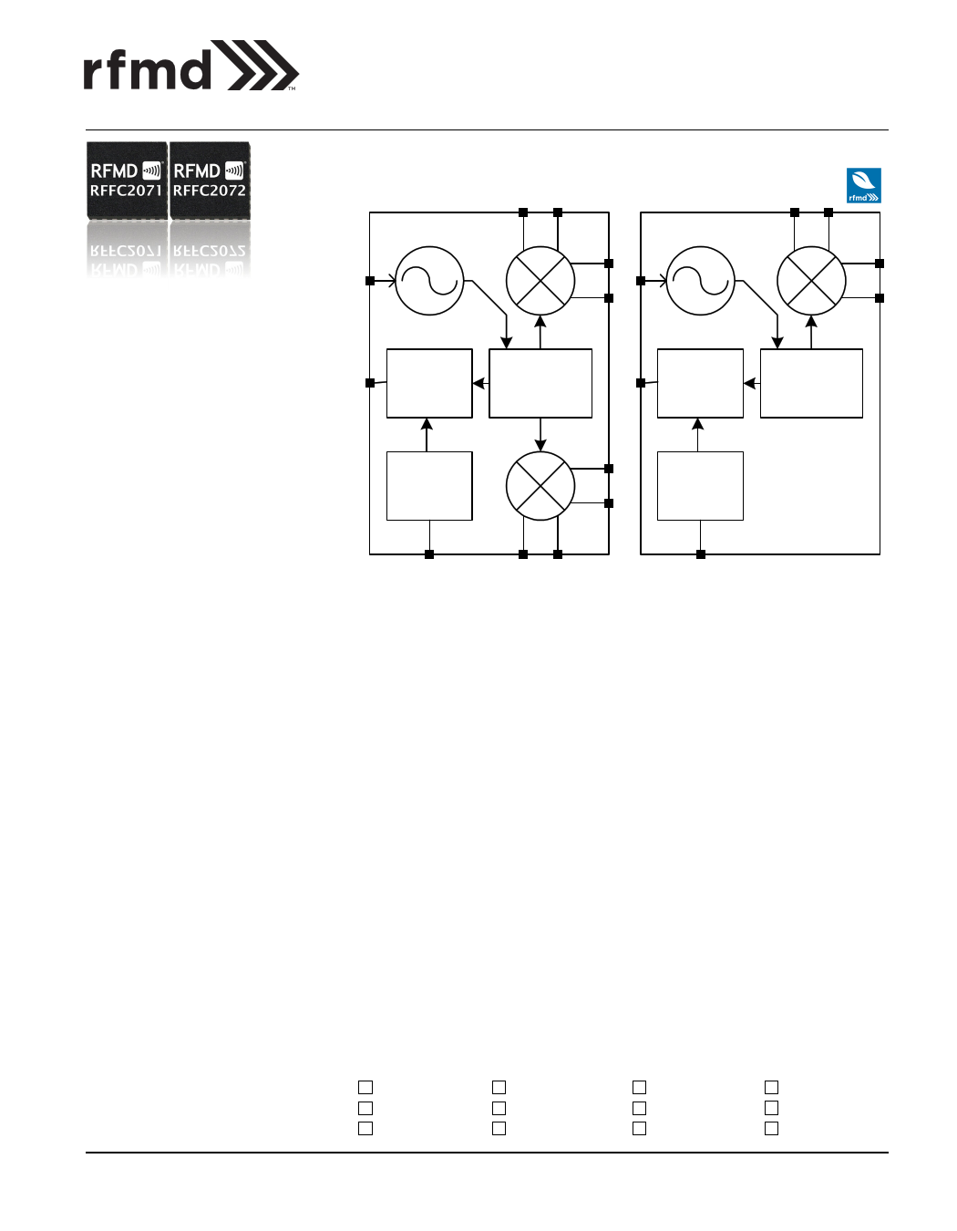
Functional Block Diagram
Product Description
The RFFC2071 and RFFC2072 are re-configurable frequency conversion devices
with integrated fractional-N phased locked loop (PLL) synthesizer, voltage con-
trolled oscillator (VCO) and either one or two high linearity mixers. The fractional-N
synthesizer takes advantage of an advanced sigma-delta modulator that delivers
ultra-fine step sizes and low spurious products. The PLL/VCO engine combined with
an external loop filter allows the user to generate local oscillator (LO) signals from
85MHz to 2700MHz. The LO signal is buffered and routed to the integrated RF mix-
ers which are used to up/down-convert frequencies ranging from 30MHz to
2700MHz. The mixer bias current is programmable and can be reduced for applica-
tions requiring lower power consumption. Both devices can be configured to work
as signal sources by bypassing the integrated mixers. Device programming is
achieved via a simple 3-wire serial interface. In addition, a unique programming
mode allows up to four devices to be controlled from a common serial bus. This
eliminates the need for separate chip-select control lines between each device and
the host controller. Up to six general purpose outputs are provided, which can be
used to access internal signals (the LOCK signal, for example) or to control front
end components. Both devices operate with a 2.7V to 3.3V power supply.
Optimum Technology Matching® Applied
GaAs HBT
GaAs MESFET
InGaP HBT
SiGe BiCMOS
Si BiCMOS
SiGe HBT
GaAs pHEMT
Si CMOS
Si BJT
GaN HEMT
BiFET HBT
LDMOS
DS140110
RF MICRO DEVICES®, RFMD®, Optimum Technology Matching®, Enabling Wireless Connectivity™, PowerStar®, POLARIS™ TOTAL RADIO™ and UltimateBlue™ are trademarks of RFMD, LLC. BLUETOOTH is a trade-
mark owned by Bluetooth SIG, Inc., U.S.A. and licensed for use by RFMD. All other trade names, trademarks and registered trademarks are the property of their respective owners. ©2012, RF Micro Devices, Inc.
7628 Thorndike Road, Greensboro, NC 27409-9421 · For sales or technical
support, contact RFMD at (+1) 336-678-5570 or [email protected].
1 of 23
1 page 
RFFC2071/2072
Theory of Operation
The RFFC2071 and RFFC2072 are wideband RF frequency converter chips which include a fractional-N synthesizer and a low
noise VCO core. The RFFC2071 has an LO signal multiplexer, two LO buffer circuits, and two RF mixers. The RFFC2072 has a
single LO buffer circuit and one RF mixer. Both devices have an integrated voltage reference and low drop out regulators sup-
plying critical circuit blocks such as the VCOs and synthesizer. Synthesizer programming, device configuration and control are
achieved through a mixture of hardware and software controls. All on-chip registers are programmed through a simple 3-wire
serial interface.
VCO
The VCO core in the RFFC2071 and RFFC2072 consists of three VCOs which, in conjunction with the integrated LO dividers of
/2 to /32, cover the LO range of 85MHz to 2700MHz. Each VCO has 128 overlapping bands which are used to achieve low VCO
gain and optimal phase noise performance across the whole tuning range. The chip automatically selects the correct VCO (VCO
auto-select) and VCO band (VCO coarse tuning) to generate the desired LO frequency based on the values programmed into
the PLL1 and PLL2 registers banks.
The VCO auto-select and VCO coarse tuning are triggered every time ENBL is taken high, or if the PLL re-lock self clearing bit is
programmed high. Once the correct VCO and band have been selected the PLL will lock onto the correct frequency. During the
band selection process, fixed capacitance elements are progressively connected to the VCO resonant circuit until the VCO is
oscillating approximately at the correct frequency. The output of this band selection, CT_CAL, is made available in the read-
back register. A value of 127 or 0 in this register indicates that the coarse tuning was unsuccessful, and this will also be indi-
cated by the CT_FAILED flag also available in the read-back register. A CT_CAL value between 1 and 126 indicates a success-
ful calibration, the actual value being dependent on the desired frequency as well as process variation for a particular device.
The band select process will center the VCO tuning voltage at about 1.0V, compensating for manufacturing tolerances and pro-
cess variation as well as environmental factors including temperature. In applications where the device is left enabled at the
same LO frequency for some time, it is recommended that automatic band selection be performed for every 30°C change in
temperature. This assumes an active loop filter.
The RFFC2071 and RFFC2072 feature a differential LO input to allow the mixer to be driven from an external LO source. The
fractional-N PLL can be used with an external VCO driven into this LO input, which may be useful to reduce phase noise in
some applications. This may also require an external op-amp, dependant on the tuning voltage required by the external VCO.
In the RFFC2071 the LO signal is routed to mixer 1, mixer 2, or both mixers depending on the state of the MODE pin (or MODE
bit if under software control) and the value of the FULLD bit. Setting FULLD high puts the device into Full Duplex mode and both
mixers are enabled.
Fractional-N PLL
The RFFC2071 and RFFC2072 contain a charge pump-based fractional-N phase locked loop (PLL) for controlling the three
VCOs. The PLL includes automatic calibration systems to counteract the effects of process and environmental variations,
ensuring repeatable loop response and phase noise performance. As well as the VCO auto-select and coarse tuning, there is a
loop filter calibration mechanism which can be enabled if required. This operates by adjusting the charge pump current to
maintain loop bandwidth. This can be useful for applications where the LO is tuned over a wide frequency range.
The PLL has been designed to use a reference frequency of between 10MHz and 104MHz from an external source, which is
typically a temperature controlled crystal oscillator (TCXO). A reference divider (divide by 1 to divide by 7) is supplied and
should be programmed to limit the frequency at the phase detector to a maximum of 52MHz.
Two PLL programming banks are provided, the first bank is preceded by the label PLL1 and the second bank is preceded by the
label PLL2. For the RFFC2071 these banks are used to program mixer 1 and mixer 2 respectively, and are selected automati-
cally as the mixer is selected using MODE. For the RFFC2072 mixer 2 and register bank PLL2 are normally used.
The VCO outputs are first divided down in a high frequency prescalar. The output of this high frequency prescalar then enters
the N divider, which is a fractional divider containing a dual-modulus prescaler and a digitally spur-compensated fractional
DS140110
7628 Thorndike Road, Greensboro, NC 27409-9421 · For sales or technical
support, contact RFMD at (+1) 336-678-5570 or [email protected].
5 of 23
5 Page 
Loop
Filter
Control
Lines
3-Wire
Serial
Bus
MODE
ENBL
RESET
ENX
SDATA
SCLK
RFFC2071/2072
Detailed Functional Block Diagram
+3V
OP2
Ext LO
RFXF8553
4:1 Balun
RFXF9503
1:1 Balun
IP2
Mixer 2
Pre-
scaler
Sequence
generator
N
divider
Phase
detector
/2n
[n=1..5]
Reference
divider
Mixer 1
+3V
51K
+3V
OP1
GPO
Lock
Flag
XO
RFXF9503
1:1 Balun
RFXF8553
4:1 Balun
IP1
RFFC2071 Only
DS140110
7628 Thorndike Road, Greensboro, NC 27409-9421 · For sales or technical
support, contact RFMD at (+1) 336-678-5570 or [email protected].
11 of 23
11 Page | ||
| Páginas | Total 23 Páginas | |
| PDF Descargar | [ Datasheet RFFC2071.PDF ] | |
Hoja de datos destacado
| Número de pieza | Descripción | Fabricantes |
| RFFC2071 | 2.7GHz RF SYNTHESIZER/VCO | RF Micro Devices |
| RFFC2071A | 2.7GHz RF SYNTHESIZER/VCO | RF Micro Devices |
| RFFC2071A | 2.7GHz RF SYNTHESIZER/VCO | RF Micro Devices |
| RFFC2072 | 2.7GHz RF SYNTHESIZER/VCO | RF Micro Devices |
| Número de pieza | Descripción | Fabricantes |
| SLA6805M | High Voltage 3 phase Motor Driver IC. |
Sanken |
| SDC1742 | 12- and 14-Bit Hybrid Synchro / Resolver-to-Digital Converters. |
Analog Devices |
|
DataSheet.es es una pagina web que funciona como un repositorio de manuales o hoja de datos de muchos de los productos más populares, |
| DataSheet.es | 2020 | Privacy Policy | Contacto | Buscar |