|
|
|
PDF AAT2522 Data sheet ( Hoja de datos )
| Número de pieza | AAT2522 | |
| Descripción | Step-Down Regulator | |
| Fabricantes | Skyworks | |
| Logotipo | ||
Hay una vista previa y un enlace de descarga de AAT2522 (archivo pdf) en la parte inferior de esta página. Total 19 Páginas | ||
|
No Preview Available !
DATA SHEET
AAT2522
Dual High-Current, Low-Noise, Step-Down Regulator
General Description
The AAT2522 is a SwitchReg, dual, high-current, step-
down converter with an input voltage range of 2.7V to
5.5V and an adjustable output voltage from 0.6V to VIN.
The 1.4MHz switching frequency enables the use of small
external components. The compact footprint and high
efficiency make the AAT2522 an ideal choice for portable
applications.
The AAT2522 delivers load currents up to 3.0A maximum
output current per regulator. Ultra-low RDS(ON) integrated
MOSFETs and 100% duty cycle operation make the
AAT2522 an ideal choice for high output-voltage, high
current applications which require a low dropout thresh-
old.
The AAT2522 provides excellent transient response and
high output accuracy across the operating range. The
AAT2522’s unique architecture requires no external com-
pensation components, and produces reduced ripple and
spectral noise. Over-temperature and short-circuit pro-
tection safeguard the AAT2522 and system components
from damage.
The AAT2522 is available in a Pb-free, space-saving
16-pin 3mm x 4mm TDFN package. The product is rated
over an operating temperature range of -40°C to +85°C.
Features
• Dual 3.0A Peak Output Current Regulators
• 2.7V to 5.5V Input Voltage Range
• Adjustable Output Voltage (0.6V to VIN)
• 100% Duty-Cycle, Low-Dropout Operation
• Integrated 120mΩ High-Side Power MOSFET
• Integrated 85mΩ Low-Side Power MOSFET
• Low Noise Light Load Mode
• No External Compensation Required
• Very Low 90μA No-Load Operating Current
• <1μA Shutdown Current
• Up to 95% Efficiency
• 1.4MHz Switching Frequency
• Overload and Short-Circuit Protection
• Over-Temperature Protection
• Internal Voltage Ramped Soft-Start
• Temperature Range: -40°C to +85°C
• 16-pin 3mm x 4mm TDFN Package
Applications
• Digital Cameras and Camcorders
• Netbooks and Nettops
• Portable DVD and Media Devices
• Power-Over-Ethernet
• Set-Top Boxes
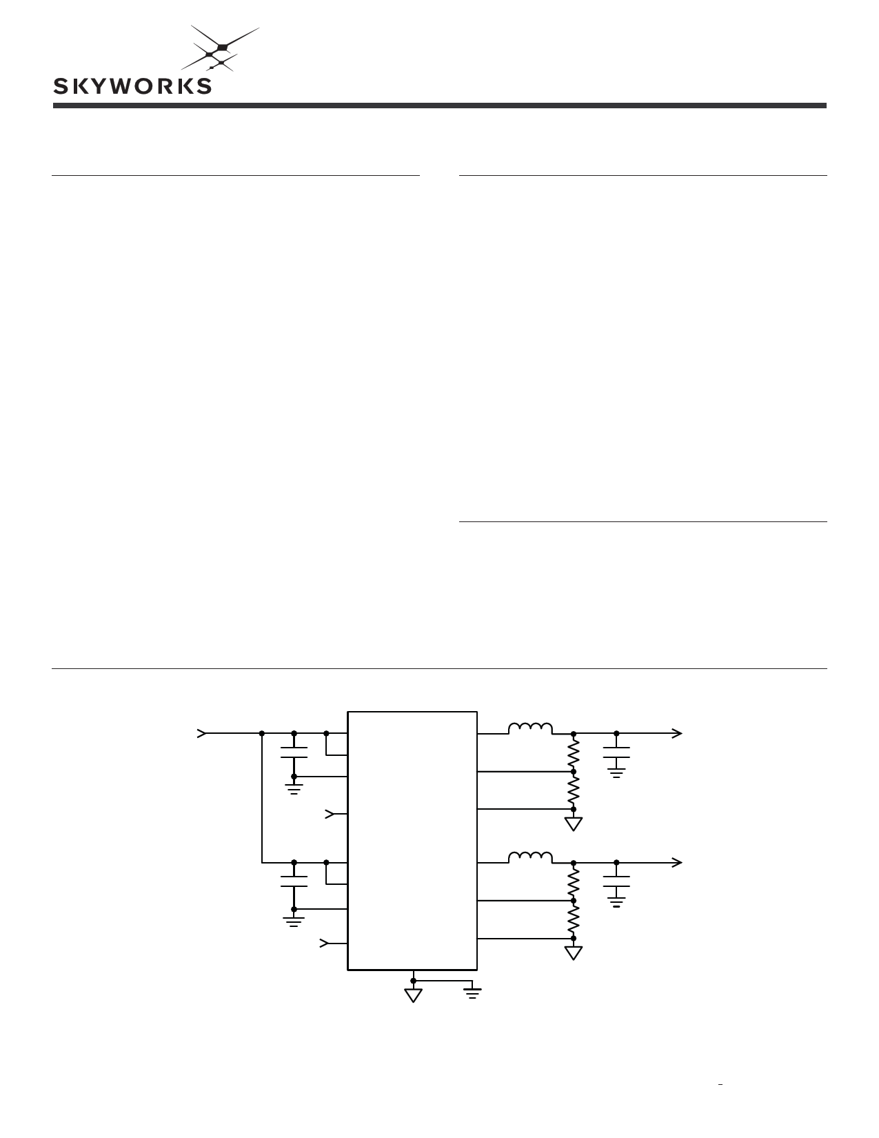
Typical Application
VIN
2.7V to 5.5V
ON/OFF
ON/OFF
IN1
VCC1
PGND1
LX1
FB1
EN1 AGND1
AAT2522
IN2
VCC2
PGND2
LX2
FB2
EN2 AGND2
EP
VOUT1
0.6V to VIN
VOUT2
0.6V to VIN
Skyworks Solutions, Inc. • Phone [781] 376-3000 • Fax [781] 376-3100 • [email protected] • www.skyworksinc.com
202032A • Skyworks Proprietary Information • Products and Product Information are Subject to Change Without Notice. • June 8, 2012
1
1 page 
DATA SHEET
AAT2522
Dual High-Current, Low-Noise, Step-Down Regulator
Typical Characteristics
Step-Down Converter Efficiency vs. Load
(VOUT = 1.2V; L = 1.2µH)
100
90
80
70
VIN = 2.7V
60 VIN = 3.0V
50 VIN = 3.3V
VIN = 3.6V
40 VIN = 4.2V
30 VIN = 5.0V
VIN = 5.5V
20
0.1
1
10
100
1000
10000
Output Current (mA)
Step-Down Converter DC Regulation
(VOUT = 1.2V; L = 1.2µH)
2.0
VIN = 2.7V
1.5 VIN = 3.0V
VIN = 3.3V
1.0 VIN = 3.6V
0.5
VIN = 4.2V
VIN = 5.0V
0.0 VIN = 5.5V
-0.5
-1.0
-1.5
-2.0
0.1
1
10
100
1000
10000
Output Current (mA)
Step-Down Converter Efficiency vs. Load
(VOUT = 1.8V; L = 1.8µH)
100
90
80
70
60
50
40
30
20
0.1
1
VIN = 2.7V
VIN = 3.0V
VIN = 3.3V
VIN = 3.6V
VIN = 4.2V
VIN = 5.0V
VIN = 5.5V
10
100
1000
10000
Output Current (mA)
Step-Down Converter DC Regulation
(VOUT = 1.8V; L = 1.8µH)
2.0
VIN = 2.7V
1.5 VIN = 3.0V
VIN = 3.3V
1.0 VIN = 3.6V
VIN = 4.2V
0.5 VIN = 5.0V
0.0 VIN = 5.5V
-0.5
-1.0
-1.5
-2.0
0.1
1
10
100
1000
10000
Output Current (mA)
Step-Down Converter Efficiency vs. Load
(VOUT = 2.5V; L = 2.5µH)
100
90
80
70
60
50 VIN = 3.3V
VIN = 3.6V
40 VIN = 4.2V
30 VIN = 5.0V
VIN = 5.5V
20
0.1 1
10
100
1000
10000
Output Current (mA)
Step-Down Converter DC Regulation
(VOUT = 2.5V; L = 2.5µH)
2.0
VIN = 3.3V
1.5 VIN = 3.6V
VIN = 4.2V
1.0 VIN = 5.0V
VIN = 5.5V
0.5
0.0
-0.5
-1.0
-1.5
-2.0
0.1
1
10
100
1000
10000
Output Current (mA)
Skyworks Solutions, Inc. • Phone [781] 376-3000 • Fax [781] 376-3100 • [email protected] • www.skyworksinc.com
202032A • Skyworks Proprietary Information • Products and Product Information are Subject to Change Without Notice. • June 8, 2012
5
5 Page 
DATA SHEET
AAT2522
Dual High-Current, Low-Noise, Step-Down Regulator
Thermal protection completely disables switching when
the maximum junction temperature is detected. The
junction over-temperature threshold is 140°C with 15°C
of hysteresis. Once an over-temperature or over-current
fault condition is removed, the output voltage automati-
cally recovers.
Peak current mode control and optimized internal com-
pensation provide high loop bandwidth and excellent
response to input voltage and fast load transient events.
Soft start eliminates output voltage overshoot when the
enable or the input voltage is applied. Under-voltage
lockout prevents spurious start-up events.
Control Scheme
The AAT2522 regulators are peak current-mode, step-
down converters. The controller senses the current
through the high-side P-channel MOSFET for current
loop control, as well as short-circuit and overload protec-
tion. A fixed slope compensation signal is added to the
sensed current to maintain stability for duty cycles
greater than 50%. The resulting peak current-mode loop
appears as a voltage-programmed current source in par-
allel with the output capacitor.
The output of the voltage error amplifier programs the
current-mode loop for the necessary peak switch current
to force a constant output voltage for all load and line
conditions. Internal loop compensation terminates the
transconductance voltage error amplifier output. The
reference voltage is internally set to program the con-
verter output voltage greater than or equal to 0.6V.
Soft-Start / Enable
Soft-start limits the current surge seen at the input and
eliminates output voltage overshoot. When pulled low,
the enable input forces the AAT2522 into a low-power
non-switching state. The total input current during shut-
down is less than 1μA.
Protection Circuitry
For overload conditions, the peak input current is limit-
ed. To minimize power dissipation and stresses under
current limit and short-circuit conditions, switching is
terminated after entering current limit for a series of
pulses. Switching is terminated for seven consecutive
clock cycles after a current limit has been sensed for a
series of four consecutive clock cycles.
Thermal protection completely disables switching when
internal dissipation becomes excessive. The junction
over-temperature threshold is 140°C with 15°C of hys-
teresis. Once an over-temperature or over-current fault
conditions is removed, the output voltage automatically
recovers.
Input Under-Voltage Lockout
Internal bias of all circuits is controlled via the VCC
input. Under-voltage lockout (UVLO) guarantees suffi-
cient VIN bias and proper operation of all internal cir-
cuitry prior to activation.
Component Selection
Inductor Selection
The step-down converter uses peak current mode con-
trol with slope compensation to maintain stability for
duty cycles greater than 50%. The output inductor value
must be selected so the inductor current down slope
meets the internal slope compensation requirements.
Therefore, the inductor should be set equal to the output
voltage numeric value in μH. This guarantees that there
is sufficient internal slope compensation.
Manufacturer’s specifications list both the inductor DC
current rating, which is a thermal limitation, and the
peak current rating, which is determined by the satura-
tion characteristics. The inductor should not show any
appreciable saturation under normal load conditions.
Some inductors may meet the peak and average current
ratings yet result in excessive losses due to a high DCR.
Always consider the losses associated with the DCR and
its effect on the total converter efficiency when selecting
an inductor.
The 3.3μH CDRH6D38NP series Sumida inductor has a
15mΩ worst case DCR and a 3.5A DC current rating.
With a 3A load, the inductor DCR conduction loss is
135mW, which gives less than 1.4% loss in efficiency for
a 3A, 3.3V output.
Output Capacitor Selection
The output capacitor limits the output ripple and pro-
vides holdup during large load transitions. A 10μF to
22μF X5R or X7R ceramic capacitor typically provides
sufficient bulk capacitance to stabilize the output during
large load transitions and has the ESR and ESL charac-
teristics necessary for low output ripple.
The output voltage droop due to a load transient is domi-
nated by the capacitance of the ceramic output capacitor.
During a step increase in load current, the ceramic output
capacitor alone supplies the load current until the loop
Skyworks Solutions, Inc. • Phone [781] 376-3000 • Fax [781] 376-3100 • [email protected] • www.skyworksinc.com
202032A • Skyworks Proprietary Information • Products and Product Information are Subject to Change Without Notice. • June 8, 2012
11
11 Page | ||
| Páginas | Total 19 Páginas | |
| PDF Descargar | [ Datasheet AAT2522.PDF ] | |
Hoja de datos destacado
| Número de pieza | Descripción | Fabricantes |
| AAT2522 | Step-Down Regulator | Skyworks |
| Número de pieza | Descripción | Fabricantes |
| SLA6805M | High Voltage 3 phase Motor Driver IC. |
Sanken |
| SDC1742 | 12- and 14-Bit Hybrid Synchro / Resolver-to-Digital Converters. |
Analog Devices |
|
DataSheet.es es una pagina web que funciona como un repositorio de manuales o hoja de datos de muchos de los productos más populares, |
| DataSheet.es | 2020 | Privacy Policy | Contacto | Buscar |