|
|
|
PDF A1245 Data sheet ( Hoja de datos )
| Número de pieza | A1245 | |
| Descripción | Two Wire Hall-Effect Latch | |
| Fabricantes | Allegro MicroSystems | |
| Logotipo | ||
Hay una vista previa y un enlace de descarga de A1245 (archivo pdf) en la parte inferior de esta página. Total 13 Páginas | ||
|
No Preview Available !
A1245
Chopper-Stabilized, Two Wire Hall-Effect Latch
FEATURES AND BENEFITS
• High speed, 4-phase chopper stabilization
□□Low switchpoint drift throughout temperature range
□□Low sensitivity to thermal and mechanical stresses
• On-chip protection
□□Supply transient protection
□□Reverse battery protection
• On-board voltage regulator
□□3.0 to 24 V operation
• Solid-state reliability
• Industry leading ISO 7637-2 performance through use of
proprietary, 40 V clamping structures
PACKAGES:
Not to scale
Approximate
footprints
DESCRIPTION
The A1245 is a two-wire Hall-effect latch. The device is
produced on theAllegro™ advanced BiCMOS wafer fabrication
process, which implements a patented high frequency, 4-phase,
chopper-stabilization technique. This technique achieves
magnetic stability over the full operating temperature range,
and eliminates offsets inherent in devices with a single Hall
element that are exposed to harsh application environments.
Two-wire latches are particularly advantageous in cost-sensitive
applications because they require one less wire for operation
versus the more traditional open-collector output switches.
Additionally, the system designer inherently gains diagnostics
because there is always output current flowing, which should
be in either of two narrow ranges. Any current level not within
these ranges indicates a fault condition.
The Hall-effect latch will be in the high output current state
in the presence of a magnetic south polarity field of sufficient
magnitude and will remain in this state until a sufficient north
polarity field is present.
The device is offered in two package styles. The LH is a
SOT-23W style, miniature low profile package for surface-
mount applications. The UA is a 3-pin ultra-mini single inline
packages (SIP) for through-hole mounting. Both packages are
lead (Pb) free, with 100% matte tin leadframe plating.
3-pin ultramini SIP
1.5 × 4 × 3 mm
(suffix UA)
3-pin SOT23-W
2 × 3 × 1 mm
(suffix LH)
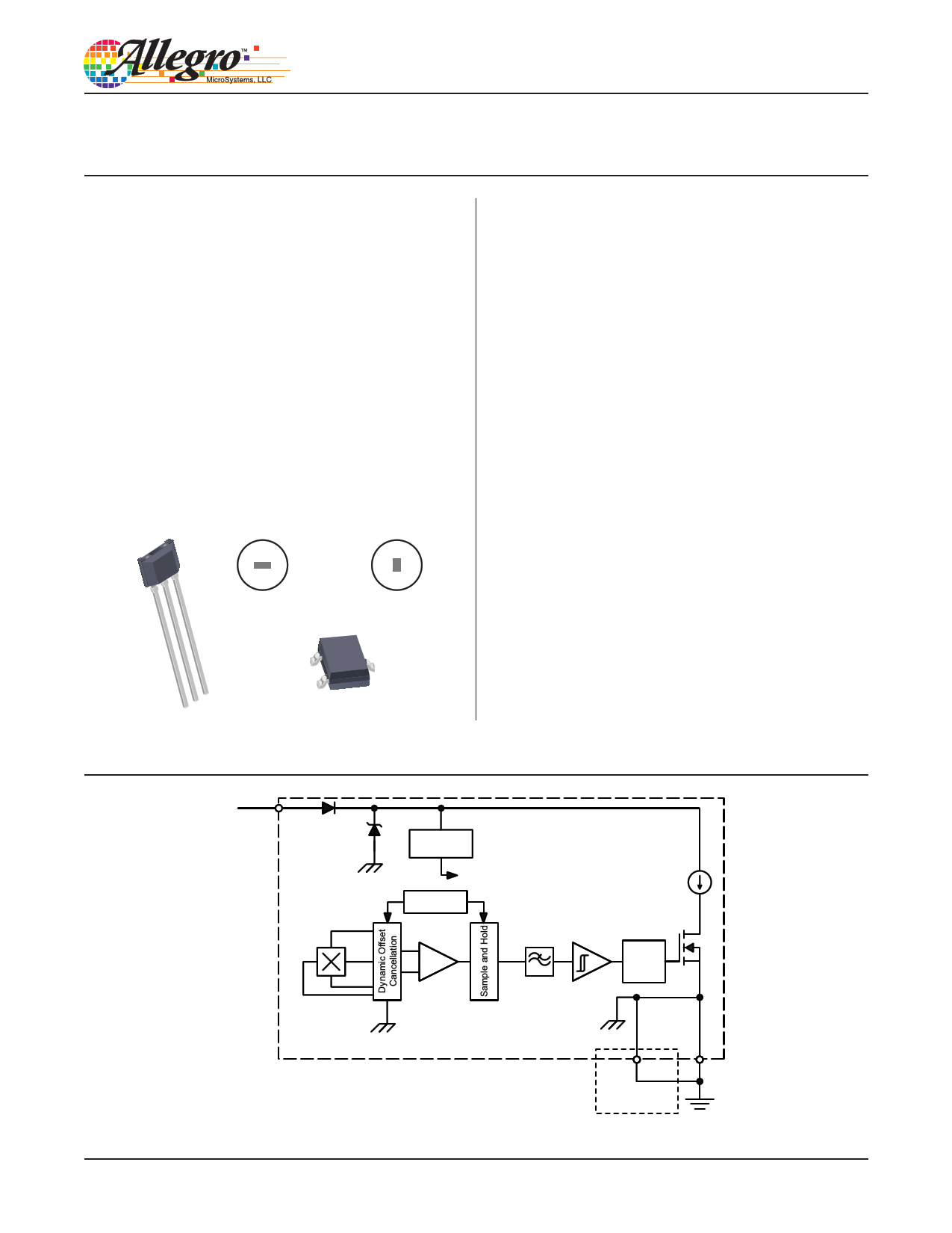
VCC
V+
Regulator
To all subcircuits
Clock/Logic
Amp
Low-Pass
Filter
Schmitt
Trigger
Polarity
A1245-DS, Rev. 1
GND
UA package only
Functional Block Diagram
GND
1 page 
A1245
Chopper-Stabilized, Two Wire
Hall-Effect Latch
THERMAL CHARACTERISTICS may require derating at maximum conditions, see application information
Characteristic
Package Thermal Resistance
Symbol
RθJA
Test Conditions*
Package LH, 1-layer PCB with copper limited to solder pads
Package LH, 2-layer PCB with 0.463 in.2 of copper area each side connected by
thermal vias
Package UA, 1-layer PCB with copper limited to solder pads
Value Units
228 ºC/W
110 ºC/W
165 ºC/W
*Additional thermal information available on Allegro Web site.
PPoowweerr DDeerraatitnigngCuCrvuerve
25
24
23
22
21
20
19
18
17
16
15
LH, 2-layer PCB
14 (RqJA = 110 ºC/W)
13
12
11 UA, 1-layer PCB
10 (RqJA = 165 ºC/W)
9
8
7
6
5 LH, 1-layer PCB
4 (RqJA = 228 ºC/W)
3
2
VCC(max)
VCC(min)
20 40 60 80 100 120 140 160 180
Temperature (ºC)
Maximum Power Dissipation versus Ambient Temperature
1900
1800
1700
1600
1500
1400
1300
1200
1100
1000
900
800
700
600
500
400
300
200
100
0
(R1θ-JlaAy=e(Rr12θP6J-AlC5ay=BºeC,1r1P/PW0aCºc)BCk,/aWPga)eckUaAge LH
(1R-θlJaAye=r2P2C8BºC, P/Wac)kage LH
20 40 60 80 100 120 140 160 180
Temperature (°C)
Allegro MicroSystems, LLC
115 Northeast Cutoff
Worcester, Massachusetts 01615-0036 U.S.A.
1.508.853.5000; www.allegromicro.com
5
5 Page 
A1245
Chopper-Stabilized, Two Wire
Hall-Effect Latch
Package Outline Drawings
2.98
+0.12
–0.08
3
D
1.49
For Reference Only – Not for Tooling Use
(Reference DWG-2840)
Dimensions in millimeters – NOT TO SCALE
Dimensions exclusive of mold flash, gate burrs, and dambar protrusions
Exact case and lead configuration at supplier discretion within limits shown
4° ±4°
A
0.180
+0.020
–0.053
2.90
+0.10
–0.20
8X 10°
REF
0.96 D
1.91
+0.19
–0.06
D
2.40
0.70
0.25 MIN
1.00
12
0.55 REF
0.25 BSC
0.95
Branded Face
Seating Plane
Gauge Plane
B PCB Layout Reference View
1.00 ±0.13
NNN
0.95 BSC
0.05
+0.10
–0.05
0.40 ±0.10
A Active Area Depth, 0.28 mm
B Reference land pattern layout; all pads a minimum of 0.20 mm from all adjacent pads;
adjust as necessary to meet application process requirements and PCB layout tolerances
C Branding scale and appearance at supplier discretion
D Hall elements, not to scale
Figure 4: Package LH, 3-Pin SOT23W
C Standard Branding Reference View
N = Last three digits of device part number
Allegro MicroSystems, LLC
115 Northeast Cutoff
Worcester, Massachusetts 01615-0036 U.S.A.
1.508.853.5000; www.allegromicro.com
11
11 Page | ||
| Páginas | Total 13 Páginas | |
| PDF Descargar | [ Datasheet A1245.PDF ] | |
Hoja de datos destacado
| Número de pieza | Descripción | Fabricantes |
| A1240A | (A1225A - A1280A) FPGAs | Actel |
| A1240A-xxxx | (A1225A - A1280A) FPGAs | Actel |
| A1240XL | Integrator Series FPGAs | Actel |
| A1240XL-xxxx | FPGAs | Actel |
| Número de pieza | Descripción | Fabricantes |
| SLA6805M | High Voltage 3 phase Motor Driver IC. |
Sanken |
| SDC1742 | 12- and 14-Bit Hybrid Synchro / Resolver-to-Digital Converters. |
Analog Devices |
|
DataSheet.es es una pagina web que funciona como un repositorio de manuales o hoja de datos de muchos de los productos más populares, |
| DataSheet.es | 2020 | Privacy Policy | Contacto | Buscar |