|
|
|
PDF ACT6311 Data sheet ( Hoja de datos )
| Número de pieza | ACT6311 | |
| Descripción | White LED/OLED Step-Up Converter | |
| Fabricantes | Active-Semi | |
| Logotipo | ||
Hay una vista previa y un enlace de descarga de ACT6311 (archivo pdf) en la parte inferior de esta página. Total 10 Páginas | ||
|
No Preview Available !
FEATURES
• Adjustable Output Voltage
• Drives OLEDs or White LEDs
• 30V High Voltage Switch
• 1MHz Switching Frequency
• Tiny Inductors and Capacitors
• Tiny SOT23-5 Package
APPLICATIONS
• OLED Applications
• Cell Phones
• Digital Cameras
• PDAs, Laptops
• MP3 Players
• GPS
ACT6311
Rev 4, 15-Nov-12
White LED/OLED Step-Up Converter
GENERAL DESCRIPTION
The ACT6311 step-up DC/DC converter is
optimized for driving OLEDs or white LEDs. It can
provide an output voltage up to 24V. The device is
capable of driving up to seven LEDs in series from a
Lithium-Ion battery, with inherent current matching
and uniform brightness.
The ACT6311 incorporates a 30V high voltage
switch. The device operates at 1MHz and allows the
use of few external components. The ACT6311 is
available in the tiny SOT23-5 package.
100
80
60
40
20
0
0
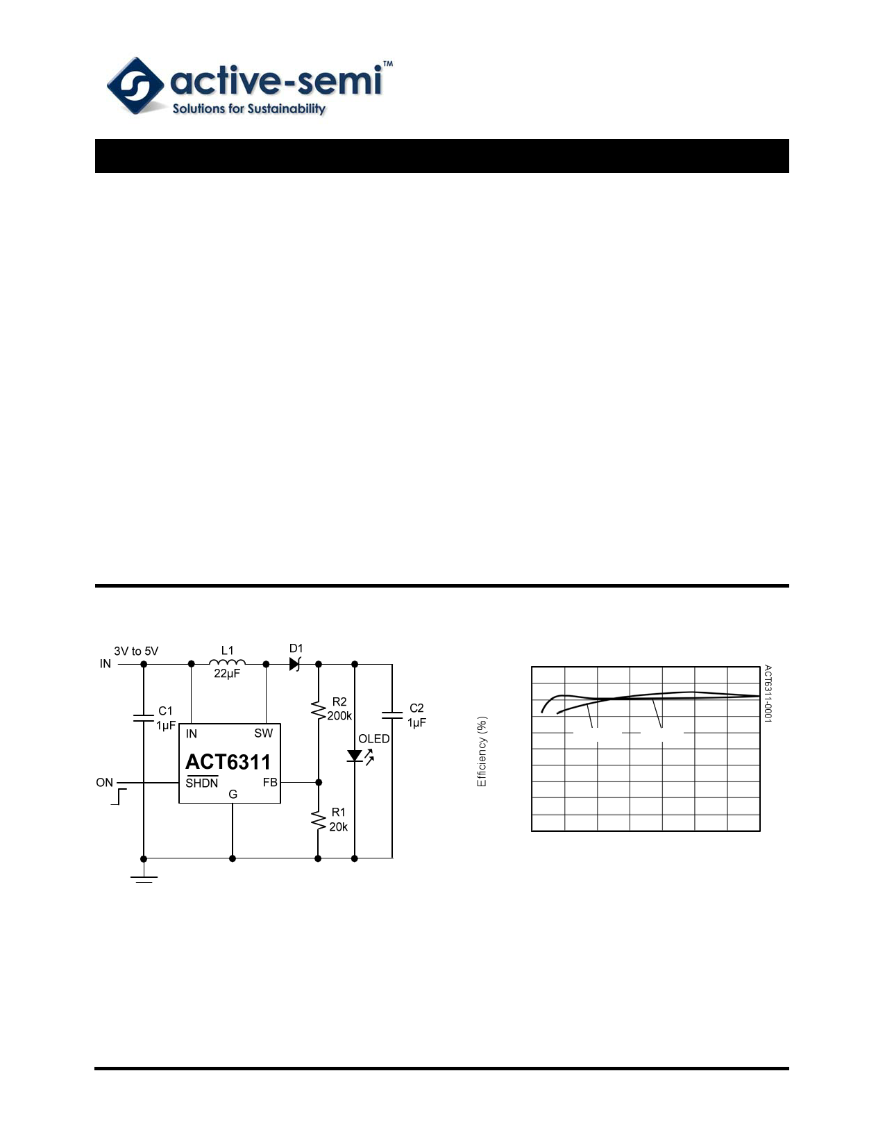
Efficiency vs. Output Current
VIN = 3.6V
VIN = 3V
VIN = 3.6V
VIN = 3V
5 10 15 20 25 30 35
Output Current (mA)
Figure 1. Typical Application Circuit
Innovative PowerTM
- 1 - www.active-semi.com
Copyright © 2012 Active-Semi, Inc.
1 page 
ACT6311
Rev 4, 15-Nov-12
APPLICATION INFORMATION
and determine R2 from the output voltage:
Inductor Selection
Table 1:
Recommended Inductors
CURRENT
PART NUMBER RATING
(MA)
DCR
(Ω)
SUPPLIER
CDRH3D16-220
350 0.5 Sumida
ELJPC220KF
160 4.0 Panasonic
LQH3C220
250 0.7 Murata
LEM2520-220
125 5.5 Taiyo Yuden
A 22µH inductor is typically used for the ACT6311.
The inductor should have low DC resistance (DCR)
and losses at 1MHz. See Table 1 for examples of
small size inductors.
Capacitor Selection
The ACT6311 only requires a 1µF input capcitor
and a 1µF output capacitor for most applications.
Ceramic capacitors are ideal for these applications.
For best performance, use X5R and X7R type
ceramic capacitors, which possess less degradation
in capacitance over voltage and temperature
ranges.
Diode Selection
The ACT6311 requires a fast recovery Schottky
diode as the rectifier. Select a low forward voltage
drop Schottky diode with a forward current (IF)
rating of 100mA to 200mA and a sufficient peak
repetitive reverse voltage (VRRM). Some suitable
Schottkky diodes are listed in Table 2.
Table 2:
Recommended Schottky Diodes
PART
NUMBER
CMDSH-3
CMDSH2-3
BAT54
IF(MA)
100
200
200
VRRM (V) SUPPLIER
30 Central
30 Central
30 Zetex
OLED Application
Figure 1 shows the feedback network necessary to
set the output voltage. Select the proper ratio of the
two feedback resistors R1 and R2 based on the
desired output voltage. Typically choose R1 = 20kΩ
R 2 = R1⎜⎛ VOUT − 1 ⎟⎞
⎝ 1 .24 V ⎠
(1)
White LED Application
The LED current is determined by the value of the
feedback resistor R1. Because the FB input of the
IC is regulated to 1.24V, the LED current is
determined by ILED = 1.24V/R1. The value of R1 for
different LED currents is shown in Table 3.
Table 3:
R1 Resistor Value Selection
ILED (MA)
5
10
12
15
20
R1 (Ω)
246
124
103.3
82.7
62
To improve efficiency, resistors R2 and R3 can be
connected as shown in Figure 4 to lower the
effective feedback voltage.
The following are dimming control methods for the
ACT6311 series white LED application.
1) PWM Signal Driving SHDN
When a PWM signal is connected to the SHDN pin,
the ACT6311 is turned on and off alternately under
the control of the PWM signal. The current through
the LEDs is either zero or full scale. By changing
the duty cycle of the PWM signal (typically 1kHz to
10kHz), a controlled average current is obtained.
2) DC Voltage Control
Figure 5 shows an application in which a DC
voltage is used to adjust the LED current. The LED
current increases when VDC is lower than VFB and
decreases when VDC is higher than VFB. In Figure 5,
the LED current range of 15mA to 0mA is controlled
by VDC = 0V to 2V.
3) Filtered PWM Control
Figure 6 shows an application using a filtered PWM
signal to control dimming.
4) Logic Control
A logic signal can be used to adjust the LED current
in a discrete step, as shown in Figure 7.
Innovative PowerTM
- 5 - www.active-semi.com
Copyright © 2012 Active-Semi, Inc.
5 Page | ||
| Páginas | Total 10 Páginas | |
| PDF Descargar | [ Datasheet ACT6311.PDF ] | |
Hoja de datos destacado
| Número de pieza | Descripción | Fabricantes |
| ACT6310 | White LED Step-Up Converter | Active-Semi |
| ACT6311 | White LED/OLED Step-Up Converter | Active-Semi |
| ACT631SMX-2 | crystal suitable | Advanced Crystal Technology |
| ACT631SMX-4 | crystal suitable | Advanced Crystal Technology |
| Número de pieza | Descripción | Fabricantes |
| SLA6805M | High Voltage 3 phase Motor Driver IC. |
Sanken |
| SDC1742 | 12- and 14-Bit Hybrid Synchro / Resolver-to-Digital Converters. |
Analog Devices |
|
DataSheet.es es una pagina web que funciona como un repositorio de manuales o hoja de datos de muchos de los productos más populares, |
| DataSheet.es | 2020 | Privacy Policy | Contacto | Buscar |