|
|
|
PDF PCF0G471MCL1GS Data sheet ( Hoja de datos )
| Número de pieza | PCF0G471MCL1GS | |
| Descripción | Aluminum Electrolytic Capacitor | |
| Fabricantes | Nichicon | |
| Logotipo | ||
Hay una vista previa y un enlace de descarga de PCF0G471MCL1GS (archivo pdf) en la parte inferior de esta página. Total 3 Páginas | ||
|
No Preview Available !
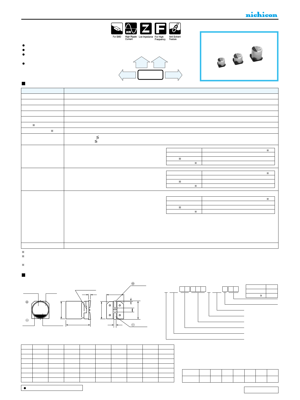
CONDUCTIVE POLYMER ALUMINUM SOLID ELECTROLYTIC CAPACITORS
CF Chip Type, Standard
series
Ultra-low ESR, High ripple current.
Load life of 2000 hours at 105°C.
SMD type : Lead free reflow soldering condition at 260°C
peak correspondence.
Compliant to the RoHS directive (2002/95/EC).
CV
High
Voltage
CG
Higher
Capacitance,
CS Long Life
CF
Low ESR CJ
Specifications
Item
Performance Characteristics
Category Temperature Range – 55 to +105°C
Rated Voltage Range
2.5 to 25V
Rated Capacitance Range 3.3 to 1500µF
Capacitance Tolerance
± 20% at 120Hz, 20°C
Tangent of loss angle (tan δ) Less than or equal to the specified value at 120Hz, 20°C
ESR ( 1)
Less than or equal to the specified value at 100kHz, 20°C
Leakage Current ( 2) Less than or equal to the specified value. After 2 minutes' application of rated voltage at 20°C
Temperature Characteristics
(Max.Impedance Ratio)
Z+105°C / Z+20°C 1.25
Z– 55°C / Z+20°C 1.25
(100kHz)
Endurance
The specifications listed at right shall be met when the
capacitors are restored to 20°C after the rated voltage is
applied for 2000 hours at 105°C
Capacitance change
tan δ
ESR ( 1)
Leakage current ( 2)
Within ± 20% of the initial capacitance value ( 3)
150% or less than the initial specified value
150% or less than the initial specified value
Less than or equal to the initial specified value
Damp Heat
(Steady State)
The specifications listed at right shall be met when the
capacitors are restored to 20°C after the rated voltage is
applied for 1000 hours at 60°C, 90% RH.
Capacitance change
tan δ
ESR ( 1)
Leakage current ( 2)
Within ± 20% of the initial capacitance value ( 3)
150% or less than the initial specified value
150% or less than the initial specified value
Less than or equal to the initial specified value
Resistance to
Soldering Heat
Marking
After soldering the capacitor under the soldering conditions
prescribed here, the capacitor shall meet the specifications listed
at right, provided that it's temperature profile is measured at the
capacitor top and the terminal.
Pre-heating shall be done at 150 to 200°C and for 60 to 180 sec.
The duration for over +230°C temperature at capacitor surface
shall not exceed 60 seconds.
In the case of peak temp, less than 250°C, reflow soldering shall
be two times maximum.
In the case of peak temp, less than 260°C, reflow soldering shall
be once.
Measurement for solder temperature profile shall be made at the
capacitor top and the terminal.
Navy blue print on the case top
Capacitance change
tan δ
ESR ( 1)
Leakage current ( 2)
Within ± 10% of the initial capacitance value ( 3)
130% or less than the initial specified value
130% or less than the initial specified value
Less than or equal to the initial specified value
1 ESR should be measured at both of the terminal ends closest where the terminals protrude through the plastic platform.
2 Conditioning : If any doubt arises, measure the leakage current after the voltage treatment of applying DC rated voltage continuously to the capacitor for 120
minutes at 105°C.
3 Initial value : The value before test of examination of resistance to soldering.
Dimensions
Capacitance
Lot No.
Plastic platform
0.3 MAX.
C±0.2
Positive
Type numbering system (Example : 6.3V 150µF)
1 2 3 4 5 6 7 8 9 10 11 12 13 14
PC F 0 J 1 5 1 MC L 1 GS
Taping code
φD Code
4 to 6.3 5.5L GB
5 to 10 L 6 GS
Series
Voltage ( j:6.3v)
L
+0.1
- 0.4
Negative
H
(mm)
Size φ4 × 5.5L φ5 × 6L φ6.3 × 5.5L φ6.3 × 6L φ8 × 7L φ8 × 12L φ10 × 8L φ10 × 10L φ10 × 12.7L
φD 4.0 5.0 6.3 6.3 8.0 8.0 10.0 10.0 10.0
L 5.4 5.9 5.4 5.9 6.9 11.9 7.9 9.9 12.6
A 5.0 6.0 7.3 7.3 9.0 9.0 11.0 11.0 11.0
B 4.3 5.3 6.6 6.6 8.3 8.3 10.3 10.3 10.3
C 4.3 5.3 6.6 6.6 8.3 8.3 10.3 10.3 10.3
E 1.0 1.6 2.1 2.1 3.2 3.2 4.6 4.6 4.6
H 0.5 to 0.8 0.5 to 0.8 0.5 to 0.8 0.5 to 0.8 0.8 to 1.1 0.8 to 1.1 0.8 to 1.1 0.8 to 1.1 0.8 to 1.1
Configuration
Capacitance toleranc (±20%)
Rated capacitance (150µF)
Rated voltage (6.3V)
Series name
Type
Size code
Voltage
V 2.5 4 6.3 10 16 20 25
Code e g j A C D E
Dimension table in next page.
CAT.8100Z
1 page | ||
| Páginas | Total 3 Páginas | |
| PDF Descargar | [ Datasheet PCF0G471MCL1GS.PDF ] | |
Hoja de datos destacado
| Número de pieza | Descripción | Fabricantes |
| PCF0G471MCL1GS | Aluminum Electrolytic Capacitor | Nichicon |
| Número de pieza | Descripción | Fabricantes |
| SLA6805M | High Voltage 3 phase Motor Driver IC. |
Sanken |
| SDC1742 | 12- and 14-Bit Hybrid Synchro / Resolver-to-Digital Converters. |
Analog Devices |
|
DataSheet.es es una pagina web que funciona como un repositorio de manuales o hoja de datos de muchos de los productos más populares, |
| DataSheet.es | 2020 | Privacy Policy | Contacto | Buscar |