|
|
|
PDF WM8758B Data sheet ( Hoja de datos )
| Número de pieza | WM8758B | |
| Descripción | Stereo CODEC | |
| Fabricantes | Wolfson Microelectronics | |
| Logotipo | ||
Hay una vista previa y un enlace de descarga de WM8758B (archivo pdf) en la parte inferior de esta página. Total 30 Páginas | ||
|
No Preview Available !
w
WM8758B
Stereo CODEC with Headphone Driver and Line Out
DESCRIPTION
FEATURES
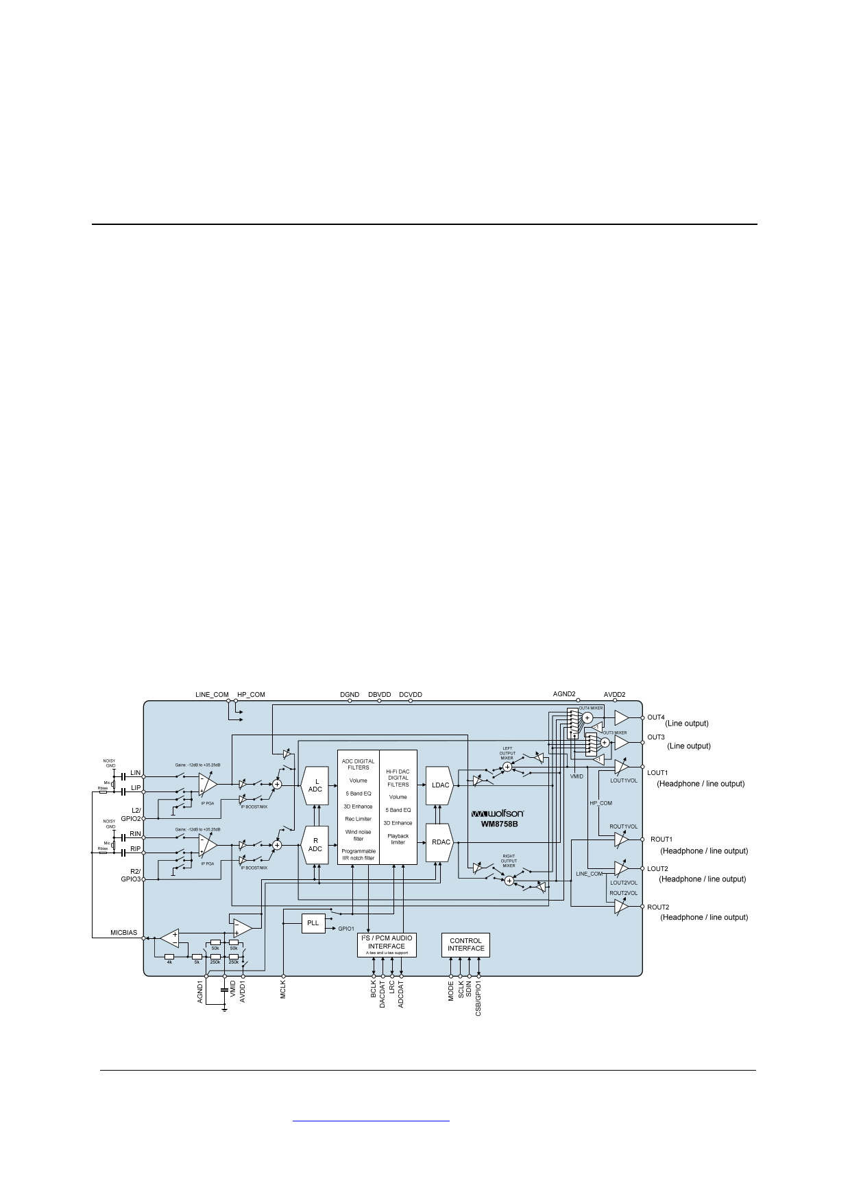
The WM8758B is a low power, high quality stereo CODEC
designed for portable applications such as MP3 audio player.
The device integrates preamps for stereo differential mics, and
drivers for headphone and differential or stereo line output.
External component requirements are reduced as no separate
microphone or headphone amplifiers are required. Headphone
and line common feedback improves crosstalk and noise
performance.
Advanced on-chip digital signal processing includes a 5-band
equaliser, a mixed signal Automatic Level Control for the
microphone or line input through the ADC as well as a purely
digital limiter function for record or playback. Additional digital
filtering options are available in the ADC path, to cater for
application filtering such as ‘wind noise reduction’ and notch
filter.
The WM8758B digital audio interface can operate in master or
slave mode with an integrated PLL.
The WM8758B operates at analogue supply voltages from 2.5V
to 3.3V, although the digital supply voltages can operate at
voltages down to 1.71V to save power. Additional power
management control enables individual sections of the chip to
be powered down under software control.
Stereo CODEC:
DAC SNR 100dB, THD -86dB (‘A’ weighted @ 48kHz)
ADC SNR 92.5dB, THD -75dB (‘A’ weighted @ 48kHz)
Headphone Driver
40mW per channel output power into 16 / 3.3V AVDD2
Line output
Mic Preamps:
Stereo Differential or mono microphone Interfaces
Programmable preamp gain
Psuedo differential inputs with common mode rejection
Programmable ALC / Noise Gate in ADC path
Low-noise bias supplied for electret microphones
Other Features:
Enhanced 3-D function for improved stereo separation
Digital playback limiter
5-band Equaliser (record or playback)
Programmable ADC High Pass Filter (wind noise reduction)
Programmable ADC Notch Filter
PLL supporting various clocks between 8MHz-50MHz
Sample rates supported (kHz): 8, 11.025, 12, 16, 22.05, 24,
32, 44.1, 48
Low power, low voltage
2.5V to 3.6V analogue supplies
1.71V to 3.6V digital supplies
5x5mm 32-lead QFN package
BLOCK DIAGRAM
APPLICATIONS
Portable audio player
WOLFSON MICROELECTRONICS plc
To receive regular email updates, sign up at http://www.wolfsonmicro.com/enews
Production Data, January 2012, Rev 4.4
Copyright 2012 Wolfson Microelectronics plc
1 page 
Production Data
PIN DESCRIPTION
PIN NAME
TYPE
1 LIP
Analogue Input
2 LIN
Analogue Input
3 L2/GPIO2
Analogue Input
4 RIP
Analogue Input
5 RIN
Analogue Input
6 R2/GPIO3
Analogue Input
7
LRC
Digital Input / Output
8
BCLK
Digital Input / Output
9 ADCDAT
Digital Output
10 DACDAT
Digital Input
11 MCLK
Digital Input
12 DGND
Supply
13 DCVDD
Supply
14 DBVDD
Supply
15
CSB/GPIO1
Digital Input / Output
16 SCLK
Digital Input
17
SDIN
Digital Input / Output
18 MODE
Digital Input
19 HP_COM
Analogue Input
20 LINE_COM
Analogue Input
21 OUT4
Analogue Output
22 OUT3
Analogue Output
23 ROUT2
Analogue Output
24 AGND2
Supply
25 LOUT2
Analogue Output
26 AVDD2
Supply
27 VMID
Reference
28 AGND1
Supply
29 ROUT1
30 LOUT1
31 AVDD1
32 MICBIAS
Analogue Output
Analogue Output
Supply
Analogue Output
WM8758B
DESCRIPTION
Left MIC pre-amp positive input
Left MIC pre-amp negative input
Left channel line input/secondary mic pre-amp positive input/GPIO2 pin
Right MIC pre-amp positive input
Right MIC pre-amp negative input
Right channel line input/secondary mic pre-amp positive input/GPIO3 pin
DAC and ADC sample rate clock
Digital audio bit clock
ADC digital audio data output
DAC digital audio data input
Master clock input
Digital ground
Digital core logic supply
Digital buffer (I/O) supply
3-Wire control interface chip select / GPIO1 pin
3-Wire control interface clock input / 2-wire control interface clock input
3-Wire control interface data input / 2-Wire control interface data input
Control interface selection
Headphone ground common feedback input
Line out ground common feedback input
Right line output / mono mix output
Left line output / mono mix output
Line output right 2
Analogue ground (return path for ROUT2/LOUT2)
Line output left 2
Analogue supply (supply for output amplifiers ROUT2/LOUT2)
Decoupling for ADC and DAC reference voltage
Analogue ground (return path for all input amplifiers, PLL, ADC and
DAC, internal bias circuits, output amplifiers LOUT1, ROUT1 and
OUT3/OUT4 on AVDD1 AGND1)
Line or headphone output right 1
Line or headphone output left 1
Analogue supply (feeds all input amplifiers, PLL, ADC and DAC, internal
bias circuits, output amplifiers LOUT1, ROUT1))
Microphone bias
Note:
It is recommended that the QFN ground paddle should be connected to analogue ground on the application PCB.
w
PD, Rev 4.4, January 2012
5
5 Page 
Production Data
WM8758B
Test Conditions
DCVDD=1.8V, AVDD1=AVDD2=3.0V, DBVDD=3.3V, TA = +25oC, 1kHz signal, fs = 48kHz, 24-bit audio data unless otherwise
stated.
PARAMETER
SYMBOL TEST CONDITIONS MIN TYP
MAX
UNIT
MIC PGA to Input Boost to OUT3/OUT4 outputs (with 10k / 50pF load)
Full-scale output voltage, 0dB
gain (Note 9)
AVDD2/3.3
Vrms
Signal to Noise Ratio (Note 5,6)
SNR
A-weighted
AVDD1=AVDD2=3.0V
A-weighted
AVDD1=AVDD2=2.5V
22Hz to 22kHz
AVDD1=AVDD2=3.0V
22Hz to 22kHz
AVDD1=AVDD2=2.5V
Total Harmonic Distortion
THD
full-scale signal
(Note 7)
AVDD1=AVDD2=3.0V
full-scale signal
AVDD1=AVDD2=2.5V
Total Harmonic Distortion + Noise THD+N
full-scale signal
(Note 7)
AVDD1=AVDD2=3.0V
full-scale signal
AVDD1=AVDD2=2.5V
Channel Separation
MIC PGA Bypass to LOUT1/ROUT1 (with 16 load)
Full-scale output voltage, 0dB
gain (Note 9)
Signal to Noise Ratio (Note 5,6)
SNR
A-weighted
AVDD1=AVDD2=3.0V
A-weighted
AVDD1=AVDD2=2.5V
22Hz to 22kHz
AVDD1=AVDD2=3.0V
22Hz to 22kHz
AVDD1=AVDD2=2.5V
Total Harmonic Distortion
THD
-5dBFS signal
(Note 7)
AVDD1=AVDD2=3.0V
-5dBFS signal
AVDD1=AVDD2=2.5V
Total Harmonic Distortion + Noise THD+N
-5dBFS signal
(Note 7)
AVDD1=AVDD2=3.0V
-5dBFS signal
AVDD1=AVDD2=2.5V
Channel separation
1kHz full scale signal
90 98
96
95.5
93.5
-84
-82
-82
-80
100
AVDD1/3.3
90 100
96
95.5
93.5
-87
-69
-85
-68
100
-75
-73
dB
dB
dB
dB
dB
dB
dB
dB
dB
Vrms
dB
dB
dB
dB
dB
dB
dB
dB
dB
w
PD, Rev 4.4, January 2012
11
11 Page | ||
| Páginas | Total 30 Páginas | |
| PDF Descargar | [ Datasheet WM8758B.PDF ] | |
Hoja de datos destacado
| Número de pieza | Descripción | Fabricantes |
| WM8758B | Stereo CODEC | Wolfson Microelectronics |
| Número de pieza | Descripción | Fabricantes |
| SLA6805M | High Voltage 3 phase Motor Driver IC. |
Sanken |
| SDC1742 | 12- and 14-Bit Hybrid Synchro / Resolver-to-Digital Converters. |
Analog Devices |
|
DataSheet.es es una pagina web que funciona como un repositorio de manuales o hoja de datos de muchos de los productos más populares, |
| DataSheet.es | 2020 | Privacy Policy | Contacto | Buscar |