|
|
|
PDF AUIRGP35B60PD Data sheet ( Hoja de datos )
| Número de pieza | AUIRGP35B60PD | |
| Descripción | WARP2 SERIES IGBT | |
| Fabricantes | International Rectifier | |
| Logotipo | ||
Hay una vista previa y un enlace de descarga de AUIRGP35B60PD (archivo pdf) en la parte inferior de esta página. Total 13 Páginas | ||
|
No Preview Available !
PD - 97675
AUTOMOTIVEGRADE AUIRGP35B60PD
WARP2 SERIES IGBT WITH
ULTRAFAST SOFT RECOVERY DIODE
Features
• NPT Technology, Positive Temperature Coefficient
• Lower VCE(SAT)
• Lower Parasitic Capacitances
• Minimal Tail Current
• HEXFRED Ultra Fast Soft-Recovery Co-Pack Diode
• Tighter Distribution of Parameters
• Higher Reliability
• Lead-Free, RoHS Compliant
• Automotive Qualified*
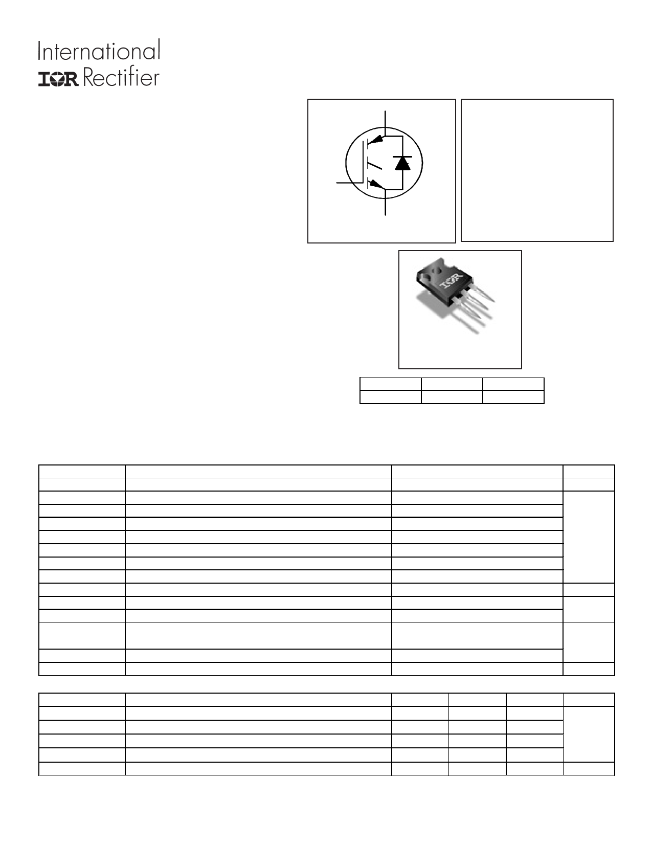
C
G
E
n-channel
VCES = 600V
VCE(on) typ. = 1.85V
@ VGE = 15V IC = 22A
Equivalent MOSFET
Parameters
RCE(on) typ. = 84mΩ
ID (FET equivalent) = 35A
Applications
• PFC and ZVS SMPS Circuits
• DC/DC Converter Charger
Benefits
• Parallel Operation for Higher Current Applications
• Lower Conduction Losses and Switching Losses
• Higher Switching Frequency up to 150kHz
G
Gate
E
C
G
TO-247AC
AUIRGP35B60PD
C
Collector
E
Emitter
Absolute Maximum Ratings
Stresses beyond those listed under “Absolute Maximum Ratings” may cause permanent damage to the device. These are stress ratings only; and
functional operation of the device at these or any other condition beyond those indicated in the specifications is not implied. Exposure to absolute-
maximum-rated conditions for extended periods may affect device reliability. The thermal resistance and power dissipation ratings are measured under
board mounted and still air conditions. Ambient temperature (TA) is 25°C, unless otherwise specified.
Parameter
Max.
Units
VCES
IC @ TC = 25°C
IC @ TC = 100°C
ICM
ILM
IF @ TC = 25°C
IF @ TC = 100°C
IFRM
VGE
PD @ TC = 25°C
PD @ TC = 100°C
TJ
TSTG
Collector-to-Emitter Voltage
Continuous Collector Current
Continuous Collector Current
Pulse Collector Current (Ref. Fig. C.T.4)
dClamped Inductive Load Current
Diode Continous Forward Current
Diode Continous Forward Current
eMaximum Repetitive Forward Current
Gate-to-Emitter Voltage
Maximum Power Dissipation
Maximum Power Dissipation
Operating Junction and
Storage Temperature Range
Soldering Temperature for 10 sec.
600
60
34
120
120
40
15
60
±20
308
123
-55 to +150
300 (0.063 in. (1.6mm) from case)
V
A
V
W
°C
Mounting Torque, 6-32 or M3 Screw
10 lbf·in (1.1 N·m)
Thermal Resistance
Parameter
Min.
Typ.
Max.
Units
RθJC (IGBT)
RθJC (Diode)
RθCS
RθJA
Thermal Resistance Junction-to-Case-(each IGBT)
Thermal Resistance Junction-to-Case-(each Diode)
Thermal Resistance, Case-to-Sink (flat, greased surface)
Thermal Resistance, Junction-to-Ambient (typical socket mount)
Weight
––– ––– 0.41
––– ––– 1.7
––– 0.50 –––
––– –––
40
––– 6.0 (0.21) –––
°C/W
g (oz)
*Qualification standards can be found at http://www.irf.com/
www.irf.com
1
05/10/11
1 page 
800
700 TJ = 25°C
TJ = 125°C
600
500
400
300
200 TJ = 125°C
100
TJ = 25°C
0
0 5 10 15 20
VGE (V)
Fig. 7 - Typ. Transfer Characteristics
VCE = 50V; tp = 10μs
10
9
8
7
6
5
4
3
2
1
0
ICE = 11A
ICE = 22A
ICE = 35A
5 10 15
VGE (V)
Fig. 9 - Typical VCE vs. VGE
TJ = 125°C
20
800
700
600 EON
500
400
EOFF
300
200
100
0
0 5 10 15 20 25 30 35 40
IC (A)
Fig. 11 - Typ. Energy Loss vs. IC
wwwTJ.i=rf1.c2o5°mDCi;oLde=c2la0m0μpHu;sVeCdE:
= 390V, RG = 3.3Ω; VGE
30ETH06 (See C.T.3)
=
15V.
AUIRGP35B60PD
10
9
8
7
6
ICE = 11A
ICE = 22A
5 ICE = 35A
4
3
2
1
0 5 10 15 20
VGE (V)
Fig. 8 - Typical VCE vs. VGE
TJ = 25°C
100
10
TJ = 150°C
TJ = 125°C
TJ = 25°C
1
0.8
1.2
1.6
2.0
2.4
Forward Voltage Drop - V FM (V)
Fig. 10 - Typ. Diode Forward Characteristics
tp = 80μs
1000
tdOFF
100
tdON
10 tF
tR
1
0
10 20 30 40
Fig. 12 - Typ. SIwCi(tcAh) ing Time vs. IC
TJ = 125°C; L = 200μH; VCE = 390V, RG = 3.3Ω; VGE = 15V.
Diode clamp used: 30ETH06 (See C.T.3)
5
5 Page 
TO-247AC Package Outline
Dimensions are shown in millimeters (inches)
AUIRGP35B60PD
TO-247AC Part Marking Information
Part Number
IR Logo
35B60PD
YWWA
XX or XX
Date Code
Y= Year
WW= Work Week
A= Automotive, LeadFree
Lot Code
TO-247AC package is not recommended for Surface Mount Application.
Note: For the most current drawing please refer to IR website at http://www.irf.com/package/
www.irf.com
11
11 Page | ||
| Páginas | Total 13 Páginas | |
| PDF Descargar | [ Datasheet AUIRGP35B60PD.PDF ] | |
Hoja de datos destacado
| Número de pieza | Descripción | Fabricantes |
| AUIRGP35B60PD | WARP2 SERIES IGBT | International Rectifier |
| AUIRGP35B60PD-E | WARP2 SERIES IGBT | International Rectifier |
| Número de pieza | Descripción | Fabricantes |
| SLA6805M | High Voltage 3 phase Motor Driver IC. |
Sanken |
| SDC1742 | 12- and 14-Bit Hybrid Synchro / Resolver-to-Digital Converters. |
Analog Devices |
|
DataSheet.es es una pagina web que funciona como un repositorio de manuales o hoja de datos de muchos de los productos más populares, |
| DataSheet.es | 2020 | Privacy Policy | Contacto | Buscar |