|
|
|
PDF GW30NC60WD Data sheet ( Hoja de datos )
| Número de pieza | GW30NC60WD | |
| Descripción | STGW30NC60WD | |
| Fabricantes | STMicroelectronics | |
| Logotipo | ||
Hay una vista previa y un enlace de descarga de GW30NC60WD (archivo pdf) en la parte inferior de esta página. Total 14 Páginas | ||
|
No Preview Available !
STGW30NC60WD
N-channel 30A - 600V - TO-247
Ultra fast switching PowerMESH™ IGBT
Features
Type
VCES
STGW30NC60WD 600V
VCE(sat)Max
@25°C
< 2.5V
IC
@100°C
30A
■ High frequency operation
■ Lower CRES / CIES ratio (no cross-conduction
susceptibility)
■ Very soft ultra fast recovery antiparallel diode
Description
Using the latest high voltage technology based on
a patented strip layout, STMicroelectronics has
designed an advanced family of IGBTs, the
PowerMESH™ IGBTs, with outstanding
performances. The suffix “W” identifies a family
optimized for very high frequency application.
Applications
■ High frequency motor controls, inverters, ups
■ HF, SMPS and PFC in both hard switch and
resonant topologies
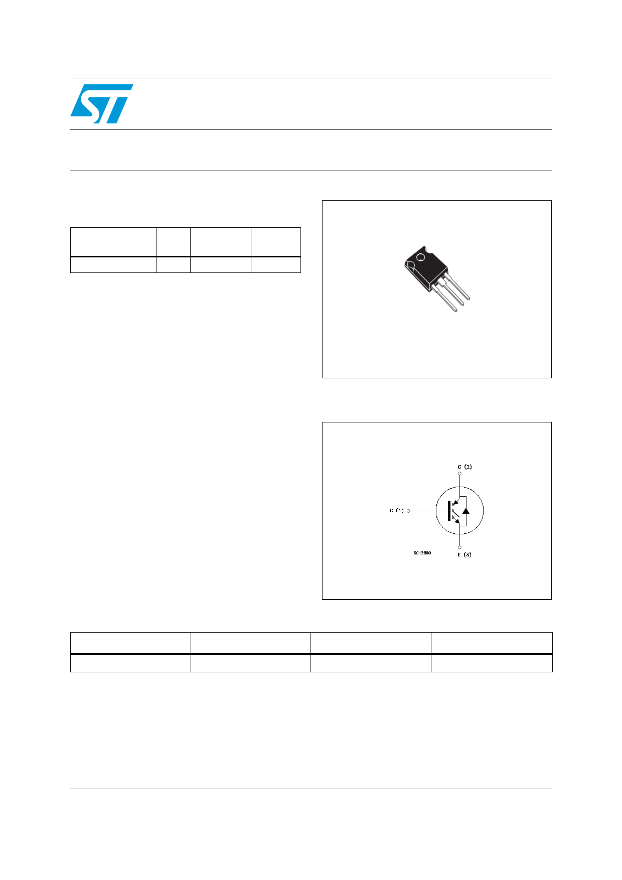
TO-247
Figure 1. Internal schematic diagram
Table 1. Device summary
Order code
Marking
STGW30NC60WD
GW30NC60WD
Package
TO-247
Packaging
Tube
July 2007
Rev 4
1/14
www.st.com
14
1 page 
STGW30NC60WD
Electrical characteristics
Table 6. Switching on/off (inductive load)
Symbol
Parameter
Test conditions
td(on)
tr
(di/dt)on
Turn-on delay time
Current rise time
Turn-on current slope
td(on)
tr
(di/dt)on
Turn-on delay time
Current rise time
Turn-on current slope
tr(Voff)
td(off)
tf
Off voltage rise time
Turn-off delay time
Current fall time
tr(Voff)
td(off)
tf
Off voltage rise time
Turn-off delay time
Current fall time
VCC = 390V, IC = 20A
RG= 10Ω, VGE= 15V,
TJ= 25°C (see Figure 17)
VCC = 390V, IC = 20A
RG= 10Ω, VGE= 15V,
TJ= 125°C (see Figure 17)
Vcc = 390V, IC = 20A,
RGE = 10Ω,
VGE=15V,TJ=25°C
(see Figure 19)
Vcc = 390V, IC = 20A,
RGE=10Ω, VGE =15V,
TJ=125°C
(see Figure 19)
Min. Typ. Max. Unit
29.5
12
1640
ns
ns
A/µs
29
13.5
1600
ns
ns
A/µs
19.5 ns
118 ns
27 ns
46 ns
151 ns
38 ns
Table 7. Switching energy (inductive load)
Symbol
Parameter
Test conditions
Min. Typ. Max. Unit
Eon(1)
Eoff(2)
Ets
Turn-on switching losses
Turn-off switching losses
Total switching losses
VCC = 390V, IC = 20A
RG= 10Ω, VGE= 15V,
Tj= 25°C (see Figure 19)
305 µJ
181 µJ
486 µJ
Eon(1)
Eoff(2)
Ets
Turn-on switching losses
Turn-off switching losses
Total switching losses
VCC = 390V, IC = 20A
RG= 10Ω, VGE= 15V,
Tj= 125°C (see Figure 19)
455 µJ
355 µJ
801 µJ
1. Eon is the tun-on losses when a typical diode is used in the test circuit in figure 2. If the IGBT is offered in
a package with a co-pak diode, the co-pack diode is used as external diode. IGBTs & Diode are at the
same temperature (25°C and 125°C)
2. Turn-off losses include also the tail of the collector current
5/14
5 Page 
STGW30NC60WD
4 Package mechanical data
Package mechanical data
In order to meet environmental requirements, ST offers these devices in ECOPACK®
packages. These packages have a Lead-free second level interconnect. The category of
second level interconnect is marked on the package and on the inner box label, in
compliance with JEDEC Standard JESD97. The maximum ratings related to soldering
conditions are also marked on the inner box label. ECOPACK is an ST trademark.
ECOPACK specifications are available at: www.st.com
11/14
11 Page | ||
| Páginas | Total 14 Páginas | |
| PDF Descargar | [ Datasheet GW30NC60WD.PDF ] | |
Hoja de datos destacado
| Número de pieza | Descripción | Fabricantes |
| GW30NC60WD | STGW30NC60WD | STMicroelectronics |
| Número de pieza | Descripción | Fabricantes |
| SLA6805M | High Voltage 3 phase Motor Driver IC. |
Sanken |
| SDC1742 | 12- and 14-Bit Hybrid Synchro / Resolver-to-Digital Converters. |
Analog Devices |
|
DataSheet.es es una pagina web que funciona como un repositorio de manuales o hoja de datos de muchos de los productos más populares, |
| DataSheet.es | 2020 | Privacy Policy | Contacto | Buscar |