|
|
|
PDF GW40N120KD Data sheet ( Hoja de datos )
| Número de pieza | GW40N120KD | |
| Descripción | STGW40N120KD | |
| Fabricantes | STMicroelectronics | |
| Logotipo | ||
Hay una vista previa y un enlace de descarga de GW40N120KD (archivo pdf) en la parte inferior de esta página. Total 15 Páginas | ||
|
No Preview Available !
STGW40N120KD
STGWA40N120KD
40 A, 1200 V short circuit rugged IGBT with Ultrafast diode
Features
■ Low on-losses
■ High current capability
■ Low gate charge
■ Short circuit withstand time 10 µs
■ IGBT co-packaged with Ultrafast free-wheeling
diode
Applications
■ Motor control
Description
This high voltage and short-circuit rugged IGBT
utilizes the advanced PowerMESH™ process
resulting in an excellent trade-off between
switching performance and low ON-state
behavior.
3
2
1
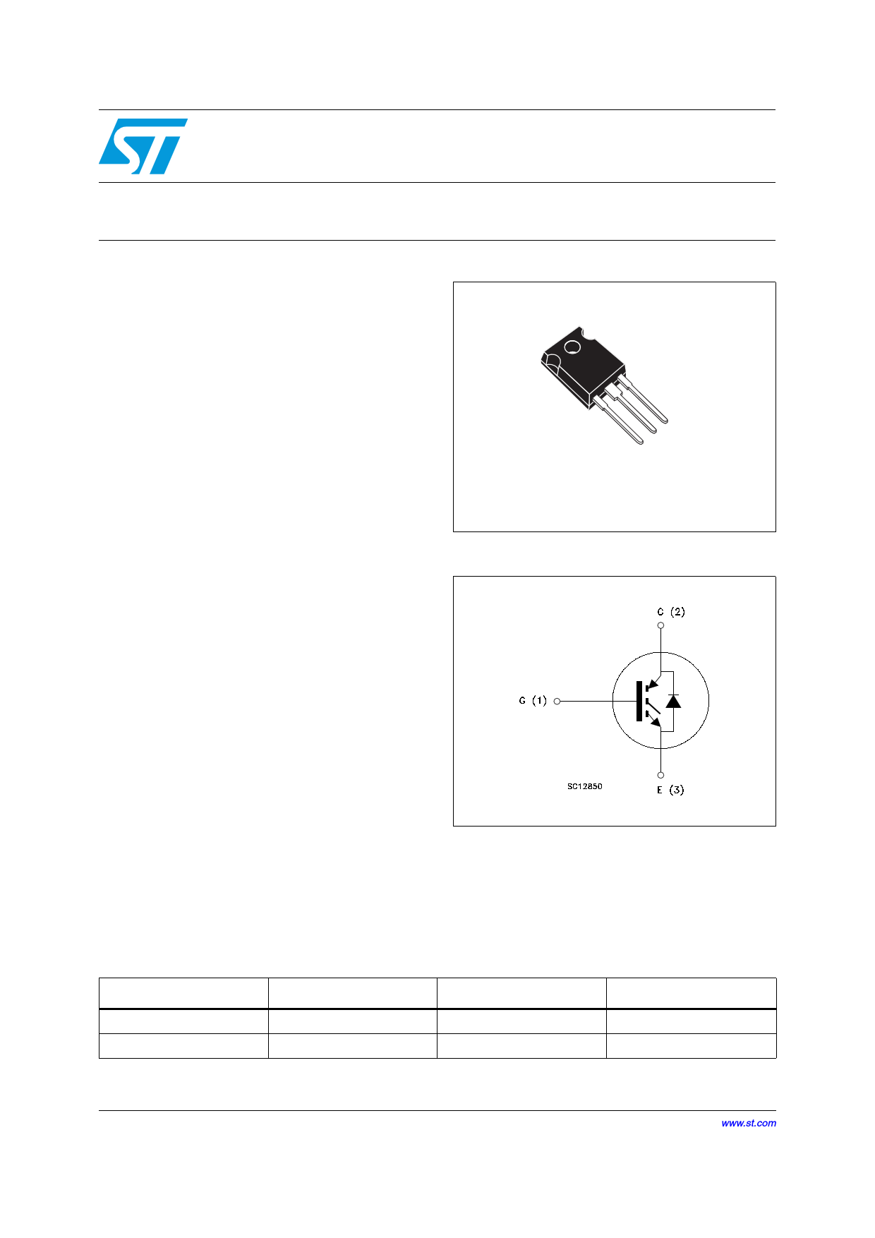
TO-247
Figure 1. Internal schematic diagram
Table 1. Device summary
Order codes
Markings
STGW40N120KD
GW40N120KD
STGWA40N120KD
GWA40N120KD
Package
TO-247
TO-247 long leads
February 2012
Doc ID 15360 Rev 5
Packaging
Tube
Tube
1/15
www.st.com
15
http://www.Datasheet4U.com
1 page 
STGW40N120KD, STGWA40N120KD
Electrical characteristics
Table 7. Switching energy (inductive load)
Symbol
Parameter
Test conditions
Min. Typ. Max. Unit
Eon (1)
Eoff (2)
Ets
Turn-on switching losses
Turn-off switching losses
Total switching losses
VCC = 960 V, IC = 30 A
RG= 10 Ω, VGE= 15 V,
(see Figure 16)
3.7 mJ
- 5.7 - mJ
9.4 mJ
Eon (1) Turn-on switching losses
Eoff (2) Turn-off switching losses
VCC = 960 V, IC = 30 A
RG= 10 Ω, VGE= 15 V,
4.7 mJ
- 9.3 - mJ
Ets Total switching losses
TJ = 125 °C (see Figure 16)
14 mJ
1. Eon is the turn-on losses when a typical diode is used in the test circuit in Figure 16. If the IGBT is offered
in a package with a co-pack diode, the co-pack diode is used as external diode. IGBTs and diode are at the
same temperature (25°C and 125°C)
2. Turn-off losses include also the tail of the collector current
Table 8. Collector-emitter diode
Symbol
Parameter
Test conditions
VF Forward on-voltage
IF = 20 A
IF = 20 A, TJ = 125 °C
trr Reverse recovery time
IF = 20 A, VR = 45 V,
Qrr Reverse recovery charge di/dt = 100 A/µs
Irrm Reverse recovery current (see Figure 19)
trr
Qrr
Reverse recovery time
Reverse recovery charge
IF = 20 A, VR = 45 V,
TJ = 125 °C,
di/dt = 100 A/µs
Irrm
Reverse recovery current
(see Figure 19)
Min. Typ. Max. Unit
1.9
--
1.7
V
V
84 ns
- 235 - nC
5.6 A
152 ns
- 722 - nC
9A
Doc ID 15360 Rev 5
5/15
5 Page 
STGW40N120KD, STGWA40N120KD
Figure 20. TO-247 drawing dimensions
Package mechanical data
0075325_G
Doc ID 15360 Rev 5
11/15
11 Page | ||
| Páginas | Total 15 Páginas | |
| PDF Descargar | [ Datasheet GW40N120KD.PDF ] | |
Hoja de datos destacado
| Número de pieza | Descripción | Fabricantes |
| GW40N120KD | STGW40N120KD | STMicroelectronics |
| Número de pieza | Descripción | Fabricantes |
| SLA6805M | High Voltage 3 phase Motor Driver IC. |
Sanken |
| SDC1742 | 12- and 14-Bit Hybrid Synchro / Resolver-to-Digital Converters. |
Analog Devices |
|
DataSheet.es es una pagina web que funciona como un repositorio de manuales o hoja de datos de muchos de los productos más populares, |
| DataSheet.es | 2020 | Privacy Policy | Contacto | Buscar |