|
|
|
PDF RDA5807FP Data sheet ( Hoja de datos )
| Número de pieza | RDA5807FP | |
| Descripción | SINGLE-CHIP BROADCAST FM RADIO TUNER | |
| Fabricantes | RDA | |
| Logotipo | ||
Hay una vista previa y un enlace de descarga de RDA5807FP (archivo pdf) en la parte inferior de esta página. Total 23 Páginas | ||
|
No Preview Available !
RDA5807FP
SINGLE-CHIP BROADCAST FM RADIO TUNER
Rev.1.2–April.2012
1 General Description
The RDA5807FP series is the newest generation
single-chip broadcast FM stereo radio tuner with fully
integrated synthesizer, IF selectivity, RDS/RBDS and
MPX decoder. The tuner uses the CMOS process,
support multi-interface and require the least external
component. The package sizes is SOP16. It is
completely adjustment-free. All these make it very
suitable for portable devices.
The RDA5807FP series has a powerful low-IF digital
audio processor, this make it have optimum sound
quality with varying reception conditions.
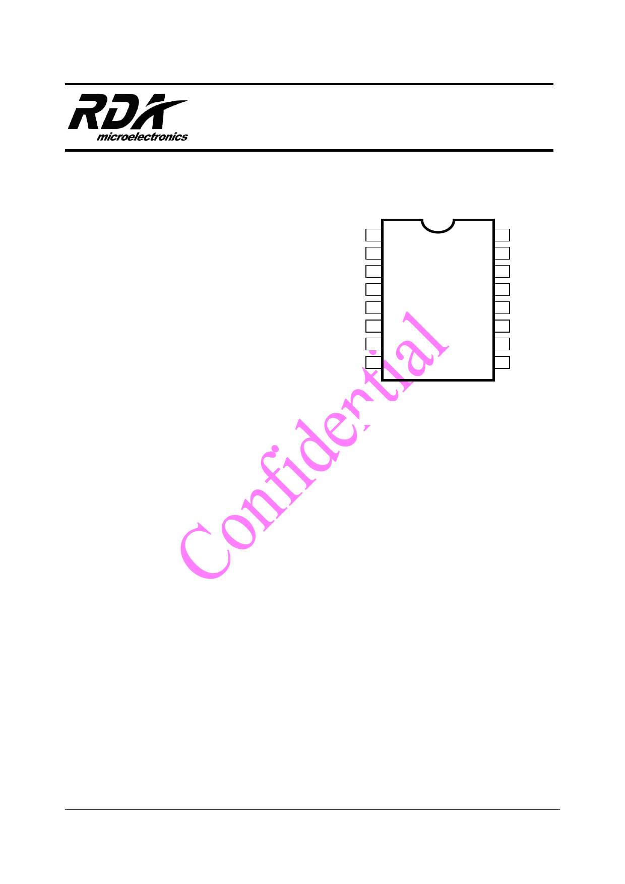
1
2
3
4
5
6
7
8
GPIO1
GPIO2
GND
GPIO3
RF GND
GND
FMIN
LOUT
RDA5807FP
GND
ROUT
GND
GND
SCLK
VDD
SDA
RCLK
16
15
14
13
12
11
10
9
The RDA5807FP series support frequency range is from 50MHz toF1ig1u5rMe1H-z1.. RDA5807FP Top View
1.1 Features
CMOS single-chip fully-integrated FM tuner
Low power consumption
Total current consumption lower than 20mA at 3.0V
power supply when under normal situation
Support worldwide frequency band
50 -108 MHz
Support flexible channel spacing mode
100KHz, 200KHz, 50KHz and 25KHz
Support RDS/RBDS
Digital low-IF tuner
Image-reject down-converter
High performance A/D converter
IF selectivity performed internally
Fully integrated digital frequency synthesizer
Fully integrated on-chip RF and IF VCO
Fully integrated on-chip loop filter
Autonomous search tuning
Support 32.768KHz crystal oscillator
Digital auto gain control (AGC)
Digital adaptive noise cancellation
Mono/stereo switch
Soft mute
High cut
Programmable de-emphasis (50/75 µs)
Receive signal strength indicator (RSSI) and SNR
Bass boost
Volume control and mute
I2S digital output interface
Line-level analog output voltage
32.768 KHz 12M,24M,13M,26M,19.2M,38.4MHz
Reference clock
Only support 2-wire bus interface
Directly support 32Ω resistance loading
Integrated LDO regulator
2.7 to 3.3 V operation voltage
SOP16 package.
Copyright © RDA Microelectronics Inc. 2006. All rights are reserved.
The information contained herein is the exclusive property of RDA and shall not be distributed, reproduced, or disclosed in whole or in
part without prior written permission of RDA.
http://www.Datasheet4U.com
1 page 
RDA Microelectronics, Inc.
3.5 Control Interface
The RDA5807FP only supports I2C control
interface.
The I2C interface is compliant to I2C Bus
Specification 2.1. It includes two pins: SCLK and
SDIO. A I2C interface transfer begins with START
condition, a command byte and data bytes, each
byte has a followed ACK (or NACK) bit, and ends
with STOP condition. The command byte includes
a 7-bit c hip a ddress ( 0010000b) a nd a R/W bit.
The ACK (or NACK) is always sent out by receiver.
When i n write t ransfer, d ata b ytes i s written out
from MCU, and when in read transfer, data bytes
is read out from RDA5807FP. There is no visible
register address in I2C interface transfers. The I2C
interface has a fixed start register address (0x02h
for write transfer and 0x0Ah for read transfer), and
an internal incremental address counter. If register
address meets the end of register file, 0x3Ah,
register address will wrap back to 0x00h. For write
transfer, MCU programs registers from register
0x02h high byte, then register 0x02h low byte,
then register 0x03h high byte, till the last register.
RDA5807FP always gives out ACK after every
byte, and MCU gives out STOP condition when
register programming is finished. For read transfer,
after command byte from MCU, RDA5807FP
sends out register 0x0Ah high byte, then register
0x0Ah low byte, then register 0x0Bh high byte, till
receives NACK from MCU. MCU gives out ACK
for data bytes besides last data byte. MCU gives
RDA5807NP FM Tuner V1.2
out NACK for last data byte, and then
RDA5807FP will return the bus to MCU, and MCU
will give out STOP condition.
3.6 I2S Audio Data Interface
The RDA5807FP supports I2S ( Inter_IC Sound
Bus) audio interface. The interface is fully
compliant with I2S bus specification. When setting
I2SEN bit high, RDA5807FP will output SCK, WS,
SD signals from GPIO3, GPIO1, GPIO2 as I2S
master and t ransmitter, t he s ample rate is
48Kbps,44.1kbps,32kbps….. RDA5807FP also
support as I2S slaver m ode and t ransmitter, t he
sample rate is less than 100kbps.
3.7 GPIO Outputs
The RDA5807FP has three GPIOs. The function
of GPIOs could programmed with bits GPIO1[1:0],
GPIO2[1:0], GPIO3[1:0] and I2SEN.
If I 2SEN is s et t o low, GPIO pi ns c ould be
programmed to output low or high or high-Z, or be
programmed to out put i nterrupt and stereo
indicator with bits GPIO1[1:0], GPIO2[1:0],
GPIO3[1:0]. G PIO2 c ould be pr ogrammed t o
output a low interrupt (interrupt will be generated
only with interrupt enable bit STCIEN is set to high)
when seek/tune process completes. GPIO3 could
be programmed to output stereo indicator bit ST.
Constant l ow, hi gh or h igh-Z f unctionality is
available regardless of the state of VDD supplies
or the ENABLE bit.
SCK
WS
SD
1 SCK
MSB
LEFT CHANNEL
RIGHT CHANNEL
LSB
1 SCK
MSB
Figure 3-2 I2S Digital Audio Format
LSB
The information contained herein is the exclusive property of RDA and shall not be distributed, reproduced, or disclosed in whole or in
part without prior written permission of RDA.
Page 5 of 23
5 Page 
RDA Microelectronics, Inc.
REG BITS
NAME
7 RSVD
6 I2S_ENABLED
5:4 GPIO3[1:0]
3:2 GPIO2[1:0]
1:0 GPIO1[1:0]
05H 15
INT _MODE
14:12
11:8
7:6
RSVD
SEEKTH[3:0]2
LNA_PORT_SEL[1:0]
5:4 RSVD
3:0 VOLUME[3:0]
06H 15
RSVD
14:13 OPEN_MODE[1:0]
12 I2S_MODE3
11 SW_LR3
10 SCLK_I_EDGE3
RDA5807NP FM Tuner V1.2
FUNCTION
DEFAULT
If 1, afc disabled.
Reserved
I2S bus enable
If 0, disabled;
If 1, enabled.
General Purpose I/O 3.
00 = High impedance
01 = Mono/Stereo indicator (ST)
10 = Low
11 = High
General Purpose I/O 2.
00 = High impedance
01 = Interrupt (INT)
10 = Low
11 = High
General Purpose I/O 1.
00 = High impedance
01 = Reserved
10 = Low
11 = High
If 0, generate 5ms interrupt;
0
00
00
00
1
If 1 , interrupt l ast unt il r ead reg0CH a ction
occurs.
Reserved
000
Seek SNR threshold value
1000
LNA input port selection bit:
10
10: FMIN
Resvered
00
DAC Gain Control Bits (Volume).
0000=min; 1111=max
Volume scale is logarithmic
When 0000, output mute and
impedance is very large
reserved
output
1111
0
Open reserved register mode.
11=open behind registers writing function
others: only open behind registers reading
function
If 0, master mode;
00
0
If 1, slave mode.
Ws relation to l/r channel.
10
If 0, ws=0 ->r, ws=1 ->l;
If 1, ws=0 ->l, ws=1 ->r.
When I2S enable
0
If 0, use normal sclk internally;
2 This value is SNR threshold for seeking, and the default value 1000 is about 32dB SNR.
3 This function is open when I2S_Enabled=1.
The information contained herein is the exclusive property of RDA and shall not be distributed, reproduced, or disclosed in whole or in
part without prior written permission of RDA.
Page 11 of 23
11 Page | ||
| Páginas | Total 23 Páginas | |
| PDF Descargar | [ Datasheet RDA5807FP.PDF ] | |
Hoja de datos destacado
| Número de pieza | Descripción | Fabricantes |
| RDA5807FP | SINGLE-CHIP BROADCAST FM RADIO TUNER | RDA |
| Número de pieza | Descripción | Fabricantes |
| SLA6805M | High Voltage 3 phase Motor Driver IC. |
Sanken |
| SDC1742 | 12- and 14-Bit Hybrid Synchro / Resolver-to-Digital Converters. |
Analog Devices |
|
DataSheet.es es una pagina web que funciona como un repositorio de manuales o hoja de datos de muchos de los productos más populares, |
| DataSheet.es | 2020 | Privacy Policy | Contacto | Buscar |