|
|
|
PDF PBL38710-1 Data sheet ( Hoja de datos )
| Número de pieza | PBL38710-1 | |
| Descripción | Subscriber Line Interface Circuit | |
| Fabricantes | Ericsson | |
| Logotipo | ||
Hay una vista previa y un enlace de descarga de PBL38710-1 (archivo pdf) en la parte inferior de esta página. Total 20 Páginas | ||
|
No Preview Available !
February 1999
PBL 387 10/1
Subscriber Line
Interface Circuit
Description
The PBL 387 10/1 ring SLIC (Subscriber Line Interface Circuit) is a bipolar integrated
circuit in 90 V technology which replaces the conventional transformer based analog
line interface and ringrelay in FITL, WLL, ISDN-TA and other telecommunications
equipment with a modern, compact solid state design. Not only is required PCB area
reduced, but less component weight and height result as well. The PBL 387 10/1 has
been optimized for low cost and to require only a minimum of external components.
The PBL 387 10/1 constant-current feed system, programmable to max 40 mA of
line current, can operate with battery supply voltages down to -21 V to reduce line
card power dissipation.
The SLIC incorporates loop current, ground key and ring trip detection functions.
Two-to four-wire and four- to two-wire voice frequency (vf) signal conversion is
accomplished by the SLIC in conjunction with either a conventional CODEC/filter or
with a programmable CODEC/filter (e.g. SLAC, SiCoFi, Combo II). The programmable
line terminating impedance could be complex or real to fit every market.
The PBL 387 10/1 package is 28-pin PLCC.
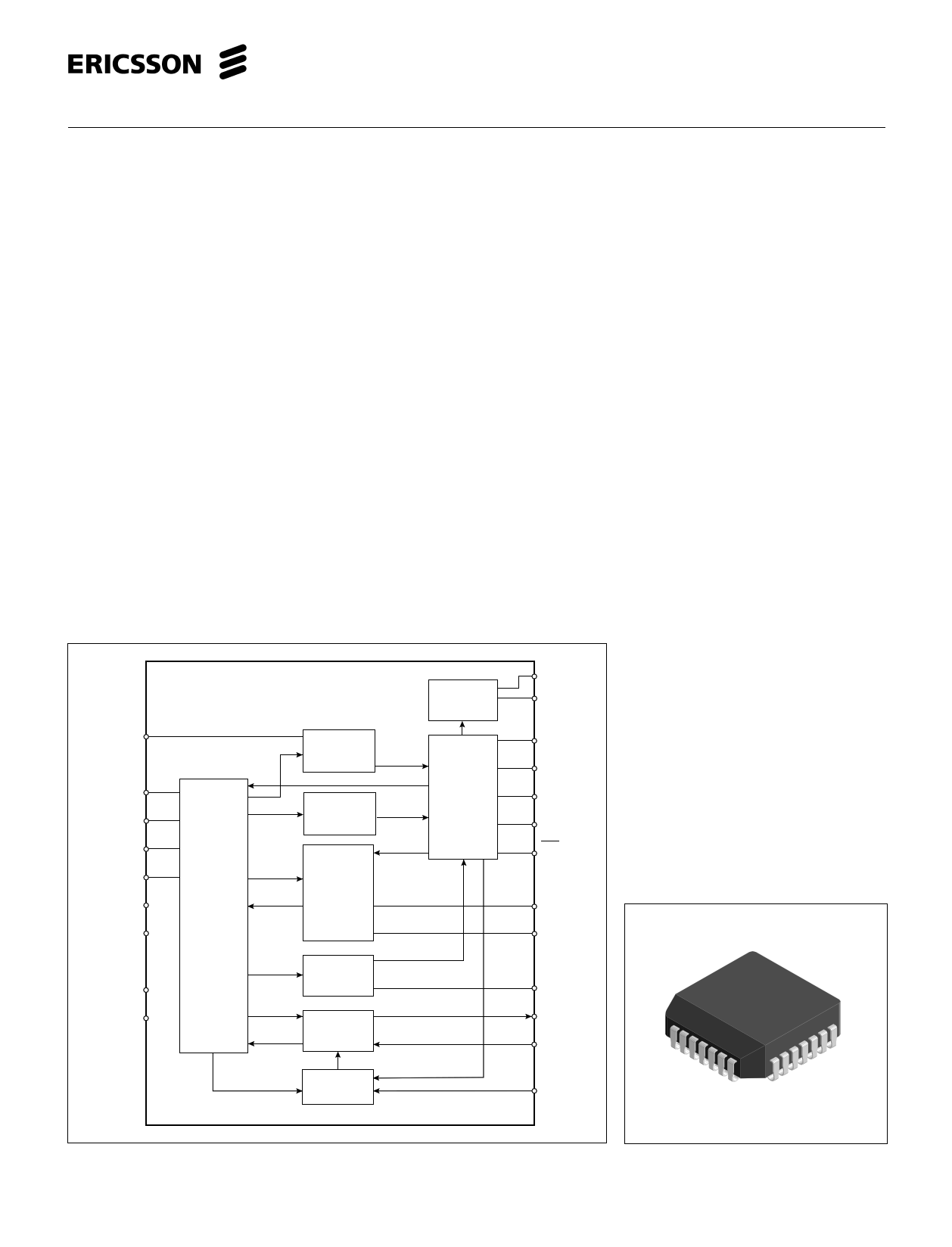
RDR
TIPX
HPR
HPT
RINGX
VCC
VEE
Two-wire
Interface
Ring Trip
Detector
Ground Key
Detector
Line Feed
Controller
and
Longitudinal
Signal
Suppression
Battery
switch
Input
Decoder and
Control
VBAT2
VBAT
C1
C2
HB
E1
DET
RDC
RSG
Key Features
· Ring SLIC eliminates ring relay and
conventional ring-generator
· Supports sine wave and trapezoidal
ringing
· -85 V battery feed for high voltage ring
signal
· On chip automatic battery switch
· Programmable battery feed
characteristics
· Battery supply voltage as low as -21 V
for power efficient line card designs
· Low on-hook power dissipation,
50 mW @-24 V battery
· Loop current, ring trip and ground key
detection functions
· Programmable loop current detector
threshold
· Programmable ring trip detector
threshold
· Hybrid function with all types of
CODEC/filter devices
· Programmable line terminating
impedance, complex or real
· On-hook transmission
· Tip-ring open circuit state for
subscriber loop power denial
AGND
BGND
Off-hook
Detector
VF Signal
Transmission
RD
VTX
3871P0B/1L
RSN
Ringing
Control
VR
28-pin PLCC
Figure 1. Block diagram.
1
http://www.Datasheet4U.com/
1 page 
PBL 387 10/1
Parameter
Frequency response
Two-wire to four-wire, g2-4
Ref
fig Conditions
Min Typ
Max
Unit
6 0.3 kHz < f < 3.4 kHz
relative to 0 dBm, 1.0 kHz. ERX = 0 V -0.2
0.2 dB
Four-wire to two-wire, g
4-2
6 0.3 kHz < f < 3.4 kHz
relative to 0 dBm, 1.0 kHz. EL = 0 V -0.2
0.2 dB
Four-wire to four-wire, g4-4
6 0.3 kHz < f < 3.4 kHz
relative to 0 dBm, 1.0 kHz. EL = 0 V -0.2
0.2 dB
Insertion loss
Two-wire to four-wire, G2-4
6 0 dBm, 1.0 kHz, Note 4
G2-4 = 20 · Log VTX , ERX = 0
VTR
-0.2
0.2 dB
Four-wire to two-wire, G
4-2
6
Gain tracking
Two-wire to four-wire
Four-wire to two-wire
6
6
Noise
Idle channel noise at two-wire
(TIPX-RINGX) or four-wire (VTX) output
Harmonic distortion
Two-wire to four-wire
Four-wire to two-wire
0 dBm, 1.0 kHz, Notes 4, 5
V
G4-2 = 20 · Log TR , EL = 0
ERX
Ref. -10 dBm, 1.0 kHz, Note 7
-40 dBm to +3 dBm
-55 dBm to -40 dBm
Ref. -10 dBm, 1.0 kHz, Note 8
-40 dBm to +3 dBm
-55 dBm to -40 dBm
C-message weighting
Psophometrical weighting
Note 6
0 dBm, 1.0 kHz test signal
0.3 kHz < f < 3.4 kHz
-0.2 0.2 dB
-0.1 0.1 dB
-0.2 0.2 dB
-0.1 0.1 dB
-0.2 0.2 dB
10 12 dBrnC
-80 -78 dBmp
-60 dB
-60 dB
Figure 6. Frequency response, insertion
loss, gain tracking.
ω1C<< RL, RL= 600 Ω
RT = 600 kΩ, RRX = 300 kΩ
RL
EL
C
VTR
ILDC
TIPX
VTX
PBL 387 10/1
RINGX RSN
RT
RRX
E RX
VTX
5
http://www.Datasheet4U.com/
5 Page 
PBL 387 10/1
VTX
PBL
387 10/1
ZT
RSN
RTX
ZB
Z RX
Figure 10. Hybrid funktion.
RFB
VT
Combination
CODEC/Filter
VRX
RF
TIP
TIPX
RING
CHP
RF
HPT
HPR
RINGX
VT + VLo
RHP / 2
1/2
1/2
RHP / 2
VR + VLo
I Lo
VT + VR
2
+ VLo
+
+
1
-
V LoRef
I Lo
VLO
R Lo
20K
I Lo / 1000
PBL 387 10/1
Figure 11. Longitudinal impedance.
Longitudinal Impedance
A feed back loop counteracts longitudi-
nal voltages at the two-wire port by
injecting longitudinal currents in opposing
phase.
Thus longitudinal disturbances will
appear as longitudinal currents and the
TIPX and RINGX terminals will
experience very small longitudinal
voltage excursions, leaving metallic volta-
ges well within the SLIC common mode
range.This is accomplished by comparing
the instantaneous two-wire longitudinal
voltage to an internal longitudinal
reference voltage, VLoRef .
VLoRef
=
VBat2
2
=
VT
+
2
VR
where VT and VR are tip and ring gro-
und referenced voltages without any
longitudinal component. As shown below
the SLIC appears as 20 Ω per wire to
longitudinal disturbances. It should be
noted that longitudinal currents may
exceed the dc loop current without distur-
bing the vf transmission. Refer to figure
11.
Circuit analysis yields:
VLo
RLo
=
ILo
1000
which reduces to
RLoT = RLoR = VLo /ILo =20kΩ/1000 = 20Ω
where:
RLo = 20 kΩ
RLoT = RLoR = longitudinal resistance/wire
VLo = longitudinal voltage at
TIPX,RINGX
ILo = longitudinal current
Capacitors CTC and CRC
The capacitors designated CTC and CRC
in figure 12, connected between TIPX
and ground as well as between RINGX
and ground, are recommended as an
addition to the overvoltage protection
network. Very fast transients, appearing
on tip and ring, may pass by the active
components in the overvoltage protection
network before they have had time to
activate and could damage the SLIC. CTC
and CRC short such very fast transients to
ground. CTC and CRC also work as RFI-
filters in conjunction with suitable series
impedances (i.e. resistances,
inductances). Resistors RF1 and RF2 may
be sufficient, but series inductances can
be added to form a second order filter.
The recommended value for CTC and CRC
is 2200 pF. Higher capacitance values
may be used, but care must be taken to
prevent degradation of either longitudinal
balance or return loss. CTC and CRC
contribute to a metallic impedance of
1/(π·f·CTC) = 1/(π·f·CRC), a TIPX to ground
impedance of 1/(2·π·f·CTC) and a RINGX
to ground impedance of 1/(2·π·f·CRC).
AC - DC Separation Capacitor, CHP
The high pass filter capacitor
connected between terminals HPT and
HPR provides the separation between
circuits sensing tip-ring dc conditions and
circuits processing ac signals. A CHP
value of 10 nF will position the low end
frequency response 3dB break point at
48 Hz (f3dB) according to f3dB=
1/(2·π·RHP·CHP) where RHP ≈ 330 kΩ.
Battery Feed
The block diagram in figure 13 shows
the PBL 38710/1 battery feed system
and figure 14 illustrates the battery feed
characteristics in the active state.
For a tip to ring dc voltage VTR less
than the saturation guard reference
voltage ,VSGRef, the SLIC emulates a
constant current feed characteristic in the
active state. The constant current is inde-
pendent of the actual battery voltage,
VBat2, connected to the SLIC.
With the tip to ring DC voltage VTR
exceeding VSGRef, the feed characteristic
changes to a nearly-constant voltage
feed. This is to prevent the tip and ring
drive amplifiers from distorting the AC
signal as might have otherwise occurred
due to insufficent voltage margin
between VTR and VBat2. Thus the SLIC
11 http://www.Datasheet4U.com/
11 Page | ||
| Páginas | Total 20 Páginas | |
| PDF Descargar | [ Datasheet PBL38710-1.PDF ] | |
Hoja de datos destacado
| Número de pieza | Descripción | Fabricantes |
| PBL38710-1 | Subscriber Line Interface Circuit | Ericsson |
| Número de pieza | Descripción | Fabricantes |
| SLA6805M | High Voltage 3 phase Motor Driver IC. |
Sanken |
| SDC1742 | 12- and 14-Bit Hybrid Synchro / Resolver-to-Digital Converters. |
Analog Devices |
|
DataSheet.es es una pagina web que funciona como un repositorio de manuales o hoja de datos de muchos de los productos más populares, |
| DataSheet.es | 2020 | Privacy Policy | Contacto | Buscar |