|
|
|
PDF A3982 Data sheet ( Hoja de datos )
| Número de pieza | A3982 | |
| Descripción | DMOS Stepper Motor Driver | |
| Fabricantes | Allegro | |
| Logotipo | ||
Hay una vista previa y un enlace de descarga de A3982 (archivo pdf) en la parte inferior de esta página. Total 11 Páginas | ||
|
No Preview Available !
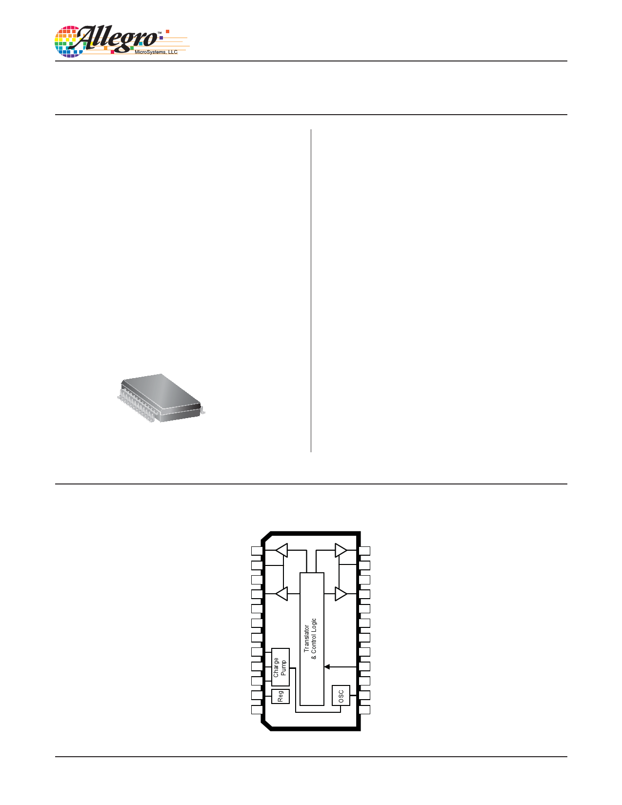
A3982
DMOS Stepper Motor Driver with Translator
Features and Benefits
▪ Low RDS(on) outputs
▪ Automatic current decay mode detection/selection
▪ Mixed and Slow current decay modes
▪ Synchronous rectification for low power dissipation
▪ Internal UVLO and thermal shutdown circuitry
▪ Crossover-current protection
Package: 24 pin SOICW with internally
fused leads (suffix LB)
Description
The A3982 is a complete stepper motor driver with built-
in translator for easy operation. It is designed to operate
bipolar stepper motors in full- and half-step modes, with an
output drive capacity of up to 35 V and ±2 A. The A3982
includes a fixed off-time current regulator which has the
ability to operate in Slow or Mixed decay modes.
The translator is the key to the easy implementation of the
A3982. Simply inputting one pulse on the STEP input drives
the motor one step. There are no phase sequence tables, high
frequency control lines, or complex interfaces to program.
The A3982 interface is an ideal fit for applications where a
complex microprocessor is unavailable or is overburdened.
The chopping control in the A3982 automatically selects
the current decay mode (Slow or Mixed). When a signal
occurs at the STEP input pin, the A3982 determines if
that step results in a higher or lower current in each of the
motor phases. If the change is to a higher current, then the
decay mode is set to Slow decay. If the change is to a lower
current, then the current decay is set to Mixed (set initially
to a fast decay for a period amounting to 31.25% of the
Not to scale
Continued on the next page…
Pin-out Diagram
OUT2A 1
SENSE2 2
VBB2 3
OUT2B 4
ENABLE 5
PGND 6
PGND 7
CP1 8
CP2 9
VCP 10
VREG 11
MS1 12
24 OUT1A
23 SENSE1
22 VBB1
21 OUT1B
20 DIR
19 PGND
18 PGND
17 REF
16 STEP
15 VDD
14 ROSC
13 RESET
26184.28C
Free Datasheet http://www.Datasheet4U.com
1 page 
A3982
DMOS Stepper Motor Driver with Translator
THERMAL CHARACTERISTICS
Characteristic
Package Thermal Resistance
Symbol
RθJA
Test Conditions*
Value Units
One-layer PCB, one-sided with copper limited to solder pads
77 ºC/W
One-layer PCB, two-sided with copper limited to solder pads and
3.57 in.2 of copper area on each side, connected to PGND pins
45 ºC/W
Four-layer PCB, based on JEDEC standard
35 ºC/W
*Additional thermal information available on Allegro Web site.
Power Dissipation versus Ambient Temperature
4.00
3.50
3.00
2.50
2.00
1.50
1.00
R
θJA
R
= 35 ºC/W
θJA = 45 ºC/W
R
θJA = 77 ºC/W
0.50
0
20 40 60 80 100 120 140 160
Temperature, TA (°C)
Allegro MicroSystems, LLC
115 Northeast Cutoff
Worcester, Massachusetts 01615-0036 U.S.A.
1.508.853.5000; www.allegromicro.com
5
Free Datasheet http://www.Datasheet4U.com
5 Page 
A3982
DMOS Stepper Motor Driver with Translator
LB Package, 24-Pin Wide Body SOIC
24
A
12
24X
0.10 C
0.41 ±0.10
15.40±0.20
4° ±4
0.27
+0.07
–0.06
24
2.20
7.50±0.10 10.30±0.33
0.84
+0.44
–0.43
SEATING C
PLANE
1.27 2.65 MAX
0.20 ±0.10
For reference only
Pins 6 and 7, and 18 and 19 internally fused
Dimensions in millimeters
(Reference JEDEC MS-013 AD)
Dimensions exclusive of mold flash, gate burrs, and dambar protrusions
Exact case and lead configuration at supplier discretion within limits shown
0.25
SEATING PLANE
GAUGE PLANE
12
0.65
B PCB Layout Reference View
A Terminal #1 mark area
B Reference pad layout (reference IPC SOIC127P1030X265-24M)
All pads a minimum of 0.20 mm from all adjacent pads; adjust as necessary
to meet application process requirements and PCB layout tolerances
9.60
1.27
Copyright ©2005-2013, Allegro MicroSystems, LLC
Allegro MicroSystems, LLC reserves the right to make, from time to time, such departures from the detail specifications as may be required to
permit improvements in the performance, reliability, or manufacturability of its products. Before placing an order, the user is cautioned to verify that
the information being relied upon is current.
Allegro’s products are not to be used in life support devices or systems, if a failure of an Allegro product can reasonably be expected to cause the
failure of that life support device or system, or to affect the safety or effectiveness of that device or system.
The information included herein is believed to be accurate and reliable. However, Allegro MicroSystems, LLC assumes no responsibility for its
use; nor for any infringement of patents or other rights of third parties which may result from its use.
For the latest version of this document, visit our website:
www.allegromicro.com
Allegro MicroSystems, LLC
115 Northeast Cutoff
Worcester, Massachusetts 01615-0036 U.S.A.
1.508.853.5000; www.allegromicro.com
11
Free Datasheet http://www.Datasheet4U.com
11 Page | ||
| Páginas | Total 11 Páginas | |
| PDF Descargar | [ Datasheet A3982.PDF ] | |
Hoja de datos destacado
| Número de pieza | Descripción | Fabricantes |
| A3980 | Automotive DMOS Microstepping Driver with Translator | Allegro MicroSystems |
| A3980KLP | Automotive DMOS Microstepping Driver with Translator | Allegro MicroSystems |
| A3982 | DMOS Stepper Motor Driver | Allegro |
| A3983 | DMOS Microstepping Driver | Allegro MicroSystems |
| Número de pieza | Descripción | Fabricantes |
| SLA6805M | High Voltage 3 phase Motor Driver IC. |
Sanken |
| SDC1742 | 12- and 14-Bit Hybrid Synchro / Resolver-to-Digital Converters. |
Analog Devices |
|
DataSheet.es es una pagina web que funciona como un repositorio de manuales o hoja de datos de muchos de los productos más populares, |
| DataSheet.es | 2020 | Privacy Policy | Contacto | Buscar |