|
|
|
PDF ACT2801 Data sheet ( Hoja de datos )
| Número de pieza | ACT2801 | |
| Descripción | 5V/1.5A Backup Battery Pack Manager | |
| Fabricantes | Active-Semi | |
| Logotipo | ||
Hay una vista previa y un enlace de descarga de ACT2801 (archivo pdf) en la parte inferior de esta página. Total 21 Páginas | ||
|
No Preview Available !
ACT2801
Rev 0, 21-Jan-14
5V/1.5A Backup Battery Pack Manager
FEATURES
Dedicated Single Chip Solution for Mobile
Power With Minimal Component Count
5V/1.5A Constant Output Current in Boost
Mode
1.5A Switching Charger
Programmable 4.1V to 4.35V Battery Voltage
95% Boost Efficiency (Vbat=4.1V)
Adaptive to 10mA-2400mA Input Sources
Battery Disconnection at Output Short
<10µA Low Battery Leakage Current at HZ
Mode During Storage
Boost Auto Turn-off at No Load and Push
Button Turn-on
Battery Over Current, Over Voltage, Over
Temperature and Short Circuit Protections
Boost Auto Startup with Load Detection
Up to 2.0A Input Current Limit with Prioritized
Power Path to Output
5V+/-100mV Output Voltage in Boost Mode
1.1MHz/0.55MHz Boost Switching Frequencies
2.2uH SMD Inductor and Low Profile Ceramic
Capacitors
4 LEDs Battery Level and Status Indication
Battery Impedance Compensation
Full Cycle of Battery Charge Management
Preconditioning, Fast Charge, Top Off and End
of Charge
Charge Current Foldback at 110°C Die
Temperature
IC Over Temperature Protection at 160°C
QFN4x4-24 Package
APPLICATIONS
Backup Battery Pack
Power Bank
Mobile Power
Standalone Battery Charger with USB Output
GENERAL DESCRIPTION
ACT2801 is a space-saving and high-performance
low-profile single-chip solution for backup battery
pack and standalone battery charger. ACT2801
integrates all the functions that a backup battery
pack needs, including switching charger, boost
converter and LED indication.
ACT2801 operates at 2.2MHz/1.1MHz for switching
charger and 1.1MHz/0.55MHz for boost converter
allowing tiny external inductor and capacitors.
ACT2801 provides a direct power path from input to
output with programmable current limit while
providing power to switching charger. Output has
higher priority than battery charger if the
programmed input current limit is reached.
ACT2801 charges battery with full cycle of
preconditioning, fast charge with constant current
and constant voltage until end of charge. The
battery charger is thermally regulated at 110°C with
charge current foldback.
ACT2801 boost converter steps battery voltage up
to 5V. Boost converter features high efficiency,
constant current regulation, short circuit protection
and over voltage protection.
ACT2801 provides 3.5mA constant currents to drive
4 LEDs to indicate battery level and charge status.
Innovative PowerTM
ActiveSwitcherTM is a trademark of Active-Semi.
-1-
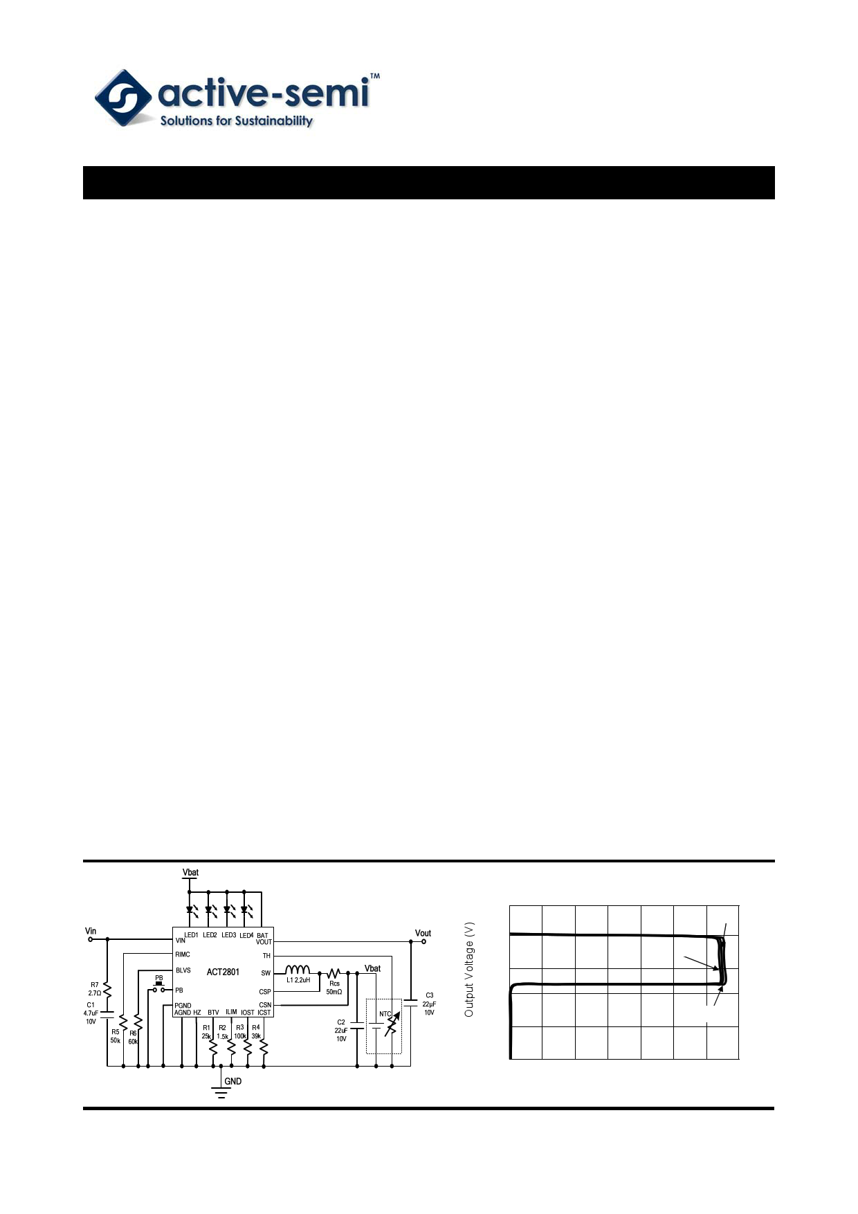
Boost CC/CV Curve
5.5
VBAT =3.7V
5.0
VBAT =3.2V
4.5
4.0
VBAT =4.1V
3.5
3.0
0 200 400 600 800 1000 1200 1400
Output Current (mA)
www.active-semi.com
Copyright © 2014 Active-Semi, Inc.
Free Datasheet http://www.Datasheet4U.com
1 page 
ACT2801
Rev 0, 21-Jan-14
ELECTRICAL CHARACTERISTICS
(VIN = 5V, TA = 25°C, unless otherwise specified.)
PARAMETER
Input Current Limit
TEST CONDITIONS
MIN TYP MAX UNIT
Input Voltage Range
4.5 5.5 V
VIN Over Voltage Protection
Input Voltage Validation Time
VIN rising, VIN_OVP
VIN_UVLO<VIN<VIN_OVP
5.5 6.0 6.5 V
32 ms
Input Current Limit Setting Range
Input Current Limit
Input Current Limit Gain
RILIM=1.2kΩ—4.8kΩ
RILIM=2kΩ
0.5
-10%
1.2
2000
2.0
+10%
A
A
Leakage Current from VOUT to VIN in Boost
Mode
Battery Discharge Current in High-Z Mode
Power Switches
VIN-to-VOUT FET on Resistance
VOUT-to-SW FET on Resistance
SW-to-PGND FET on Resistance
Buck Converter
Switching Frequency
High Side Switch Peak Current Limit
Minimum On-time
Over Temperature Protection (OTP)
3.0V<VBAT<4.35V, Ta=25℃
3.0V<VBAT<4.35V, Ta=25℃
ACT2801QL-T
ACT2801QL-T0550
OTP rising
0 10 µA
7.5 15 µA
90 mΩ
70 mΩ
75 mΩ
-15%
-15%
3.5
2.2 +15% MHz
1.1 +15% MHz
5A
100 ns
160 ℃
OTP Hysteresis
OTP falling
35 ℃
Charge Mode
Charge Current Setting Range
Charge Current Setting
Thermal Regulation Temperature
Rcs=50mΩ,RICST=20kΩ—60.4kΩ 0.5
Rcs=50mΩ, RICST=39kΩ
-10%
1.5 A
975 +10% mA
110 ℃
Battery Adjust Voltage(VBAJ)
End of Charge (EOC) Voltage
Rbtv=25kΩ
0.1
-0.5% 4.1+VBAJ 0.5%
V
V
EOC Voltage Accuracy
Rbtv=0
4.1 V
Battery Over Voltage Threshold
VBAT rising
4.6 V
Battery Over Voltage Threshold Hysteresis
VBAT falling
200 mV
Innovative PowerTM
-5-
Active-Semi Confidential―Do Not Copy or Distribute
ActiveSwitcherTM is a trademark of Active-Semi.
www.active-semi.com
Copyright © 2013 Active-Semi, Inc.
Free Datasheet http://www.Datasheet4U.com
5 Page 
APPLICATIONS INFORMATION
Battery Charge Termination Voltage
Battery charge termination voltage is set by a
resistor Rbtv connected from BTV pin to AGND as
shown in Figure 4. The battery charge termination
voltage is estimated as the following equation:
VBAT (V ) 4.1(V ) Rbtv 4 10 6 (V )
(1)
Rbtv is selected based on the battery voltage rating.
1% accuracy resistor is recommended for Rbtv.
ACT2801
Rev 0, 21-Jan-14
programmed by a resistor connected from BLVS
pin to AGND as shown in Figure 5. The following
equation shows the LED4 voltage threshold:
VBATLED4 (V ) 3.5(V ) 0.01(mA) RBLVS (k)
(2)
Figure 5. Battery level voltage shift setting circuit
Figure 4. Battery terminal voltage setting circuit
LED Status Indication
4 LEDs ON/OFF and flash show the charge status
and the remained capacity level as shown in the
table 2. The LED status is based on battery voltage
and operation modes. In charge mode, when a
battery is fully charged, flashing stops and all the 4
LEDs are solid on.
Battery level voltage shift (BLVS pin)
LED1-4 voltage thresholds are adjusted from HZ
mode during charging and discharging based on
the compensated impedance. Those thresholds are
As long as LED4 is set, all the other 3 LED
thresholds is fixed as shown in the table 3:
Table 3: 4 LED Voltage Thresholds
RBLVS (ohm)
LED1
50K
3.35V
60K
3.45V
70K
3.55V
80K
3.65V
LED2
3.60V 3.70V 3.80V 3.90V
LED3
3.75V 3.85V 3.95V 4.05V
LED4
4.00V 4.10V 4.20V 4.30V
Input Current Limit
An external resistor is used to set the input current
limit connected from ILIM pin to AGND as shown in
Figure 6. Input current limit has built-in soft startup
and current foldback control loop. The input current
limit is estimated as the following equation:
I ILIM (A)
2.4 (V)
RILIM (k )
(3)
VBAT<LED1
LED1≤VBAT<LED2
LED2≤VBAT<LED3
LED3≤VBAT<LED4
VBAT≥LED4
VBAT≥LED4
(End of Charge)
LED1
Flash
On
On
On
On
On
Table2: LED Indication
Charge Mode
PB time>100ms (Boost or HZ Mode)
LED2 LED3 LED4
LED1
LED2
LED3 LED4
Off Off Off Off Off Off Off
Flash
Off
Off
On
Off
Off Off
On Flash Off On On Off Off
On
On Flash
On
On
On Off
On
On Flash
On
On
On On
On On On On On On On
Innovative PowerTM
- 11 -
Active-Semi Confidential―Do Not Copy or Distribute
ActiveSwitcherTM is a trademark of Active-Semi.
www.active-semi.com
Copyright © 2013 Active-Semi, Inc.
Free Datasheet http://www.Datasheet4U.com
11 Page | ||
| Páginas | Total 21 Páginas | |
| PDF Descargar | [ Datasheet ACT2801.PDF ] | |
Hoja de datos destacado
| Número de pieza | Descripción | Fabricantes |
| ACT2801 | 5V/1.5A Backup Battery Pack Manager | Active-Semi |
| ACT2802 | 5V/2.5A Backup Battery Pack Manager | Active-Semi |
| ACT2802B | 5V/2.5A Backup Battery Pack Manager | Active-Semi |
| ACT2802C | 5V/2.5A Backup Battery Pack Manager | Active-Semi |
| Número de pieza | Descripción | Fabricantes |
| SLA6805M | High Voltage 3 phase Motor Driver IC. |
Sanken |
| SDC1742 | 12- and 14-Bit Hybrid Synchro / Resolver-to-Digital Converters. |
Analog Devices |
|
DataSheet.es es una pagina web que funciona como un repositorio de manuales o hoja de datos de muchos de los productos más populares, |
| DataSheet.es | 2020 | Privacy Policy | Contacto | Buscar |