|
|
|
PDF ADUM6403 Data sheet ( Hoja de datos )
| Número de pieza | ADUM6403 | |
| Descripción | (ADUM6400 - ADUM6404) Quad-Channel Isolators | |
| Fabricantes | Analog Devices | |
| Logotipo | ||
Hay una vista previa y un enlace de descarga de ADUM6403 (archivo pdf) en la parte inferior de esta página. Total 24 Páginas | ||
|
No Preview Available !
Quad-Channel Isolators with
Integrated DC-to-DC Converter
ADuM6400/ADuM6401/ADuM6402/ADuM6403/ADuM6404
FEATURES
FUNCTIONAL BLOCK DIAGRAMS
isoPower integrated, isolated dc-to-dc converter
Regulated 3.3 V or 5 V output
Up to 500 mW output power
Quad dc-to-25 Mbps (NRZ) signal isolation channels
Schmitt trigger inputs
16-lead SOIC package with 7.6 mm creepage
High temperature operation: 105°C
High common-mode transient immunity: >25 kV/μs
VDD1 1
GND1 2
VIA/VOA 3
VIB/VOB 4
VIC/VOC 5
VID/VOD 6
OSC
RECT REG
4-CHANNEL iCOUPLER CORE
ADuM6400/ADuM6401/
ADuM6402/ADuM6403/
ADuM6404
16 VISO
15 GNDISO
14 VIA/VOA
13 VIB/VOB
12 VIC/VOC
11 VID/VOD
Safety and regulatory approvals (pending)
VDDL 7
10 VSEL
UL recognition
GND1 8
9 GNDISO
5000 V rms for 1 minute per UL1577
CSA Component Acceptance Notice #5A
IEC 60950-1: 600 V rms (reinforced)
IEC 60601-1: 250 V rms (reinforced)
VDE certificate of conformity
DIN V VDE V 0884-10 (VDE V 0884-10):2006-12
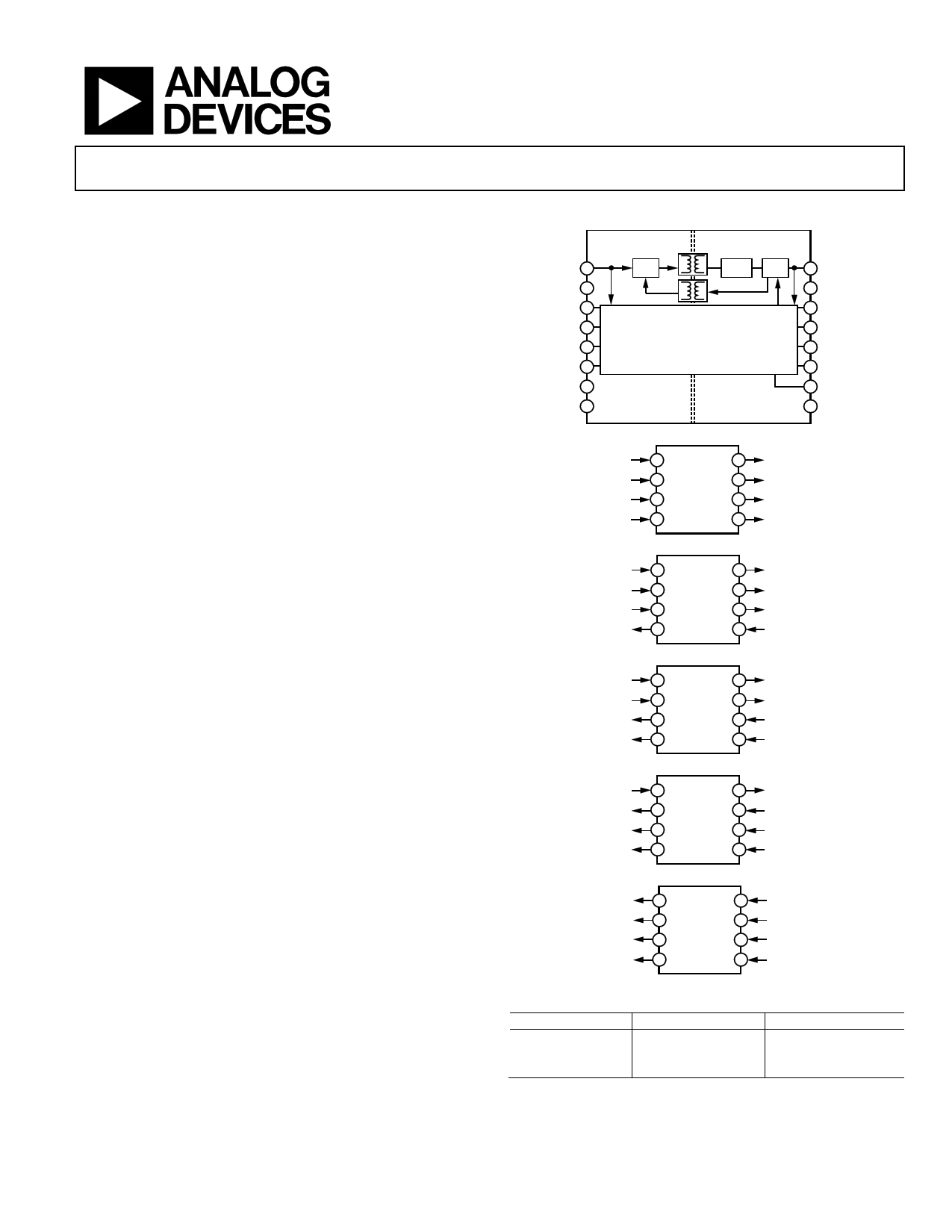
Figure 1. ADuM640x Block Diagram
VIA
3
VOA
14
VIB VOB
4 13
VIC ADuM6400 VOC
5 12
VID
6
VOD
11
VIORM = 560 V peak
Figure 2. ADuM6400
APPLICATIONS
RS-232/RS-422/RS-485 transceivers
Medical isolation
AC/dc power supply startup bias and gate drives
VIA
VIB
VIC
VOD
3 14
4 13
ADuM6401
5 12
6 11
VOA
VOB
VOC
VID
Isolated sensor interface
Figure 3. ADuM6401
GENERAL DESCRIPTION
The ADuM640x1 devices are quad-channel digital isolators with
isoPower®, an integrated, isolated dc-to-dc converter. Based on
the Analog Devices, Inc., iCoupler® technology, the dc-to-dc
VIA
VIB
VOC
VOD
3 14
4 13
ADuM6402
5 12
6 11
VOA
VOB
VIC
VID
converter provides up to 500 mW of regulated, isolated power at
either 5.0 V or 3.3 V from a 5.0 V input supply, or 3.3 V from a
3.3 V supply at the power levels shown in Table 1. This eliminates
the need for a separate, isolated dc-to-dc converter in low power,
isolated designs. The iCoupler chip scale transformer technology
is used to isolate the logic signals and for the magnetic components
Figure 4. ADuM6402
VIA
VOB
VOC
VOD
3 14
4 13
ADuM6403
5 12
6 11
VOA
VIB
VIC
VID
of the dc-to-dc converter. The result is a small form factor, total
isolation solution.
The ADuM640x isolators provide four independent isolation
channels in a variety of channel configurations and data rates
(see the Ordering Guide for more information).
Figure 5. ADuM6403
VOA
VOB
VOC
VOD
3 14
4 13
ADuM6404
5 12
6 11
VIA
VIB
VIC
VID
isoPower uses high frequency switching elements to transfer
power through its transformer. Special care must be taken
during printed circuit board (PCB) layout to meet emissions
standards. Refer to the AN-0971 application note for board
layout recommendations at www.analog.com.
Figure 6. ADuM6404
Table 1. Power Levels
Input Voltage (V) Output Voltage (V)
55
5 3.3
3.3 3.3
Output Power (mW)
500
330
200
1 Protected by U.S. Patents 5,952,849; 6,873,065; 6,903,578; and 7,075,329. Other patents are pending.
Rev. 0
Information furnished by Analog Devices is believed to be accurate and reliable. However, no
responsibility is assumed by Analog Devices for its use, nor for any infringements of patents or other
rights of third parties that may result from its use. Specifications subject to change without notice. No
license is granted by implication or otherwise under any patent or patent rights of Analog Devices.
Trademarksandregisteredtrademarksarethepropertyoftheirrespectiveowners.
One Technology Way, P.O. Box 9106, Norwood, MA 02062-9106, U.S.A.
Tel: 781.329.4700
www.analog.com
Fax: 781.461.3113
©2009 Analog Devices, Inc. All rights reserved.
Free Datasheet http://www.datasheet4u.com/
1 page 
ADuM6400/ADuM6401/ADuM6402/ADuM6403/ADuM6404
ELECTRICAL CHARACTERISTICS—3.3 V PRIMARY INPUT SUPPLY/3.3 V SECONDARY ISOLATED SUPPLY
All typical specifications are at TA = 25°C, VDD1 = VISO = 3.3 V, VSEL = GNDISO. Minimum/maximum specifications apply over the entire
recommended operation range which is 3.0 V ≤ VDD1, VSEL, VISO ≤ 3.6 V; and −40°C ≤ TA ≤ +105°C, unless otherwise noted. Switching
specifications are tested with CL = 15 pF and CMOS signal levels, unless otherwise noted.
Table 6. DC-to-DC Converter Static Specifications
Parameter
Symbol Min
DC-TO-DC CONVERTER SUPPLY
Setpoint
VISO 3.0
Line Regulation
VISO (LINE)
Load Regulation
VISO (LOAD)
Output Ripple
VISO (RIP)
Output Noise
VISO (NOISE)
Switching Frequency
fOSC
PW Modulation Frequency
fPWM
Output Supply
IISO (MAX)
60
Efficiency at IISO (MAX)
IDD1, No VISO Load
IDD1 (Q)
IDD1, Full VISO Load
IDD1 (MAX)
Typ
3.3
1
1
50
130
180
625
33
14
175
Max
3.6
5
20
Unit
V
mV/V
%
mV p-p
mV p-p
MHz
kHz
mA
%
mA
mA
Test Conditions
IISO = 0 mA
IISO = 30 mA, VDD1 = 3.0 V to 3.6 V
IISO = 6 mA to 54 mA
20 MHz bandwidth, CBO = 0.1 μF||10 μF, IISO = 54 mA
CBO = 0.1 μF||10 μF, IISO = 54 mA
VISO > 3 V
IISO = 60 mA
Table 7. DC-to-DC Converter Dynamic Specifications
2 Mbps—A Grade, B Grade, C Grade
Parameter
Symbol Min
Typ Max
SUPPLY CURRENT
ADuM6400
ADuM6401
IDD1
IISO (LOAD)
IDD1
IISO (LOAD)
14
60
14
60
ADuM6402
IDD1
14
ADuM6403
ADuM6404
IISO (LOAD)
IDD1
IISO (LOAD)
IDD1
IISO (LOAD)
60
14
60
14
60
25 Mbps—C Grade
Min Typ Max
Unit Test Conditions
41 mA No VISO load
43 mA
44 mA No VISO load
42 mA
46 mA No VISO load
41 mA
47 mA No VISO load
39 mA
51 mA No VISO load
38 mA
Table 8. Switching Specifications
Parameter
SWITCHING SPECIFICATIONS
Data Rate
Propagation Delay
Pulse Width Distortion
Change vs. Temperature
Pulse Width
Propagation Delay Skew
Channel Matching
Codirectional1
Opposing Directional2
Symbol
tPHL, tPLH
PWD
PW
tPSK
tPSKCD
tPSKOD
A Grade
C Grade
Min Typ Max Min Typ Max Unit
1
60 100
40
1000
40
50
25
45 60
6
5
45
Mbps
ns
ns
ps/°C
ns
ns
50 6 ns
50 15 ns
Test Conditions
Within PWD limit
50% input to 50% output
|tPLH − tPHL|
Within PWD limit
Between any two units
1 7Codirectional channel matching is the absolute value of the difference in propagation delays between any two channels with inputs on the same side of the
isolation barrier.
2 Opposing directional channel matching is the absolute value of the difference in propagation delays between any two channels with inputs on opposing sides of the
isolation barrier.
Rev. 0 | Page 5 of 24
Free Datasheet http://www.datasheet4u.com/
5 Page 
ADuM6400/ADuM6401/ADuM6402/ADuM6403/ADuM6404
PIN CONFIGURATIONS AND FUNCTION DESCRIPTIONS
VDD1 1
16 VISO
GND1 2
15 GNDISO
VIA 3 ADuM6400 14 VOA
VIB 4 TOP VIEW 13 VOB
VIC 5 (Not to Scale) 12 VOC
VID 6
11 VOD
VDDL 7
10 VSEL
GND1 8
9 GNDISO
Figure 8. ADuM6400 Pin Configuration
Table 21. ADuM6400 Pin Function Descriptions
Pin No. Mnemonic Description
1 VDD1 Primary Supply Voltage, 3.0 V to 5.5 V. Pin 1 and Pin 7 must be connected to the same external voltage source.
2, 8 GND1
Ground 1. Ground reference for isolator primary. Pin 2 and Pin 8 are internally connected, and it is recommended that both
pins be connected to a common ground.
3 VIA
Logic Input A.
4 VIB
Logic Input B.
5 VIC
Logic Input C.
6 VID
Logic Input D.
7 VDDL Data Channel Supply Voltage, 3.0 V to 5.5 V. Pin 1 and Pin 7 must be connected to the same external voltage source.
9, 15 GNDISO
Ground Reference for Isolator Side 2. Pin 9 and Pin 15 are internally connected, and it is recommended that both pins be
connected to a common ground.
10 VSEL
Output Voltage Selection. When VSEL = VISO, the VISO setpoint is 5.0 V. When VSEL = GNDISO, the VISO setpoint is 3.3 V.
11 VOD
Logic Output D.
12 VOC
Logic Output C.
13 VOB
Logic Output B.
14 VOA
Logic Output A.
16 VISO
Secondary Supply Voltage Output for External Loads, 3.3 V (VSEL Low) or 5.0 V (VSEL High).
Rev. 0 | Page 11 of 24
Free Datasheet http://www.datasheet4u.com/
11 Page | ||
| Páginas | Total 24 Páginas | |
| PDF Descargar | [ Datasheet ADUM6403.PDF ] | |
Hoja de datos destacado
| Número de pieza | Descripción | Fabricantes |
| ADUM6400 | (ADUM6400 - ADUM6404) Quad-Channel Isolators | Analog Devices |
| ADUM6401 | (ADUM6400 - ADUM6404) Quad-Channel Isolators | Analog Devices |
| ADUM6402 | (ADUM6400 - ADUM6404) Quad-Channel Isolators | Analog Devices |
| ADUM6403 | (ADUM6400 - ADUM6404) Quad-Channel Isolators | Analog Devices |
| Número de pieza | Descripción | Fabricantes |
| SLA6805M | High Voltage 3 phase Motor Driver IC. |
Sanken |
| SDC1742 | 12- and 14-Bit Hybrid Synchro / Resolver-to-Digital Converters. |
Analog Devices |
|
DataSheet.es es una pagina web que funciona como un repositorio de manuales o hoja de datos de muchos de los productos más populares, |
| DataSheet.es | 2020 | Privacy Policy | Contacto | Buscar |