|
|
|
PDF ELM403 Data sheet ( Hoja de datos )
| Número de pieza | ELM403 | |
| Descripción | Rotary Decoder | |
| Fabricantes | ELM | |
| Logotipo | ||
Hay una vista previa y un enlace de descarga de ELM403 (archivo pdf) en la parte inferior de esta página. Total 9 Páginas | ||
|
No Preview Available !
ELM403
Rotary Decoder - 2 wire 4x Interface
Description
The ELM403 is an 8 pin integrated circuit that is
used to convert the signals from a rotary encoder
into a series of up and down output pulses. The low
power CMOS technology used ensures that only a
very small current is required over the entire 2.0 to
5.5 volt operating range.
There is no need for external filtering or
debounce circuits with the ELM403, as this is all
performed within the integrated circuit. After
debouncing the encoder signals, the ELM403 then
determines the direction of shaft rotation, and
generates the appropriate pulses at the Up or Down
output pins. The duration of these pulses can be
selected for either 0.2 or 2.0 msec.
The ELM403 provides 4x decoding of a rotary
encoder signal. If your application requires 2x
decoding, please see the ELM402 (it is identical to
the ELM403 in every respect, except that it provides
2x decoding).
Applications
• Digital audio potentiometer controls
• Variable voltage or temperature circuits
• Positioning controls
• Tuning circuits
Features
• Low power CMOS design
• Wide supply range – 2.0 to 5.5 volts
• Complete debouncing of the encoder inputs
• No external filtering needed
• 4x decoding
• Startup delay timer
• High current drive outputs
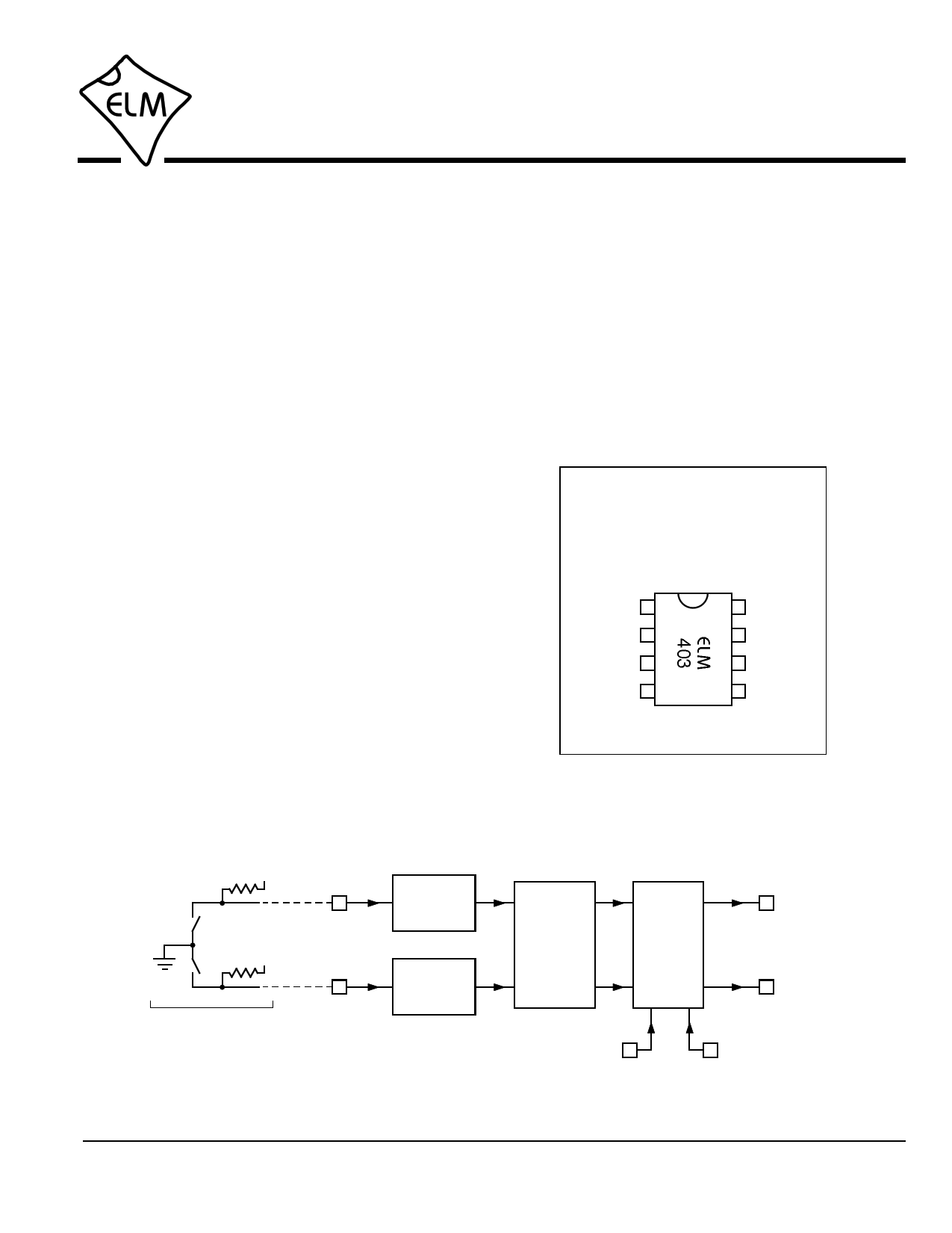
Connection Diagram
PDIP and SOIC
(top view)
VDD 1
A2
B3
Pulse 4
Width
8 VSS
7 Up
6 Down
5 Output
Invert
Block Diagram
VDD
A
Debounce
2
Circuit
VDD
B
Debounce
3
Circuit
Direction
Decoding
Output
Logic
7 Up
6 Down
Rotary
Encoder
Pulse 4
Width
5 Output
Invert
ELM403DSA
Elm Electronics – Circuits for the Hobbyist
www.elmelectronics.com
1 of 9
Free Datasheet http://www.datasheet4u.com/
1 page 
ELM403
Rotary Encoders
A rotary encoder (sometimes referred to as a
quadrature encoder) is a device that produces digital
(on/off) outputs in response to rotary, or circular,
motion. It is often constructed such that it looks very
much like a potentiometer, or audio volume control
(see the picture of a typical device, at the right).
As the encoder shaft is turned, internal contacts
open and close, creating two waveforms that are
ideally separated in phase by 90 degrees (ie ‘in
quadrature’). Actually, you need to provide external
‘pullup’ resistors and a power supply to create these
waveforms, as the contacts themselves can not do
this. An ideal waveform from a rotary encoder would
look like this:
A
B
Figure 1. Quadrature Waveforms
Due to the 90 degree phase difference, when one
waveform changes, the other is always stable. By
noting the direction of the change and the level of the
other input at that time, you can determine the
direction of motion of the shaft.
Rotary encoders are not ideal, however. Due to
their construction, and variations in shaft speed, the
A typical rotary encoder
waveforms are not perfectly square with the 50% duty
cycles shown. Figure 2 shows a captured trace from a
real rotary encoder that is more representative of what
you will typically find. Note that the two ‘scope
channels (1 and 2) represent the encoder outputs A
and B, respectively. The ch 1 (A) waveform leads the
ch 2 (B) waveform, which usually means that the shaft
is turning in a clockwise direction.
The first rising edge of the channel 2 waveform
shows another problem that occurs with moving
mechanical contacts - multiple pulses due to bounce.
When two contacts meet, the moving one will tend to
bounce, like a ball does when it is dropped on the
floor. Each bounce results in an electrical connection
being made, then broken, which will look like multiple
inputs to a fast electronic circuit. Various mechanical
means are used to reduce the amount of bounce, but it
can never really be eliminated. The following section
discusses how the ELM403 uses electronic means to
remove the bounce.
ELM403DSA
Figure 2. Actual Rotary Encoder waveform
Elm Electronics – Circuits for the Hobbyist
www.elmelectronics.com
5 of 9
Free Datasheet http://www.datasheet4u.com/
5 Page | ||
| Páginas | Total 9 Páginas | |
| PDF Descargar | [ Datasheet ELM403.PDF ] | |
Hoja de datos destacado
| Número de pieza | Descripción | Fabricantes |
| ELM401 | Rotary Encoder Debounce Circuit | ELM |
| ELM402 | Rotary Decoder | ELM |
| ELM403 | Rotary Decoder | ELM |
| ELM404 | Rotary Decoder | ELM |
| Número de pieza | Descripción | Fabricantes |
| SLA6805M | High Voltage 3 phase Motor Driver IC. |
Sanken |
| SDC1742 | 12- and 14-Bit Hybrid Synchro / Resolver-to-Digital Converters. |
Analog Devices |
|
DataSheet.es es una pagina web que funciona como un repositorio de manuales o hoja de datos de muchos de los productos más populares, |
| DataSheet.es | 2020 | Privacy Policy | Contacto | Buscar |