|
|
|
PDF DS3503 Data sheet ( Hoja de datos )
| Número de pieza | DS3503 | |
| Descripción | Stepper Potentiometer | |
| Fabricantes | Maxim Integrated | |
| Logotipo | ||
Hay una vista previa y un enlace de descarga de DS3503 (archivo pdf) en la parte inferior de esta página. Total 13 Páginas | ||
|
No Preview Available !
Rev 1; 3/09
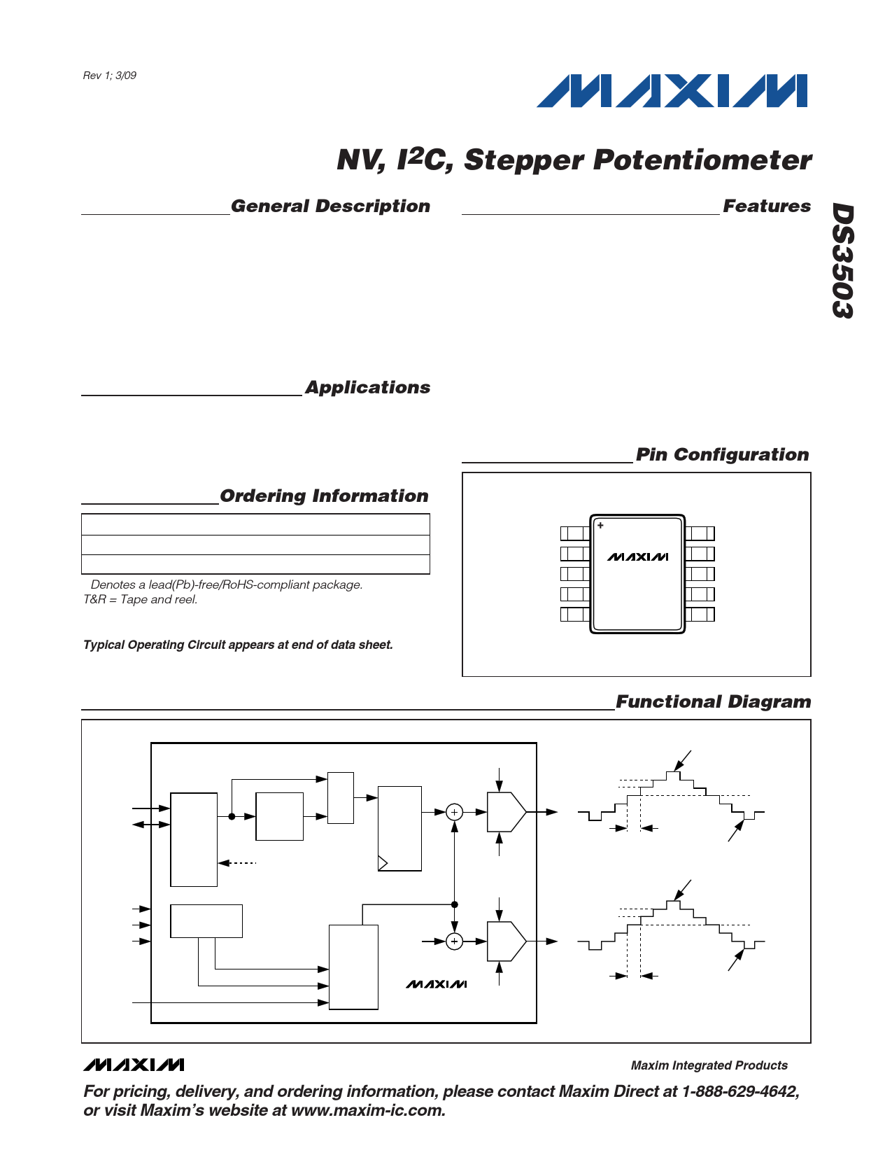
NV, I2C, Stepper Potentiometer
General Description
The DS3503 features two synchronized stepping digital
potentiometers: one 7-bit potentiometer with RW as its
output, and another potentiometer with Y as its output.
Both potentiometers reference the RH and RL terminals
and feature an output voltage range of up to 15.5V. In
addition, both potentiometer outputs can be stepped
up and down by configuring the control registers.
Programming is accomplished by an I2C-compatible
interface that can operate at speeds of up to 400kHz.
Applications
TFT-LCD VCOM Calibration
Instrumentation and Industrial Controls
Mechanical Potentiometer Replacement
Ordering Information
PART
TEMP RANGE
PIN-PACKAGE
DS3503U+
-40°C to +100°C
10 μSOP
DS3503U+T&R
-40°C to +100°C
10 μSOP
+Denotes a lead(Pb)-free/RoHS-compliant package.
T&R = Tape and reel.
Typical Operating Circuit appears at end of data sheet.
Features
♦ 128 Wiper Tap Points
♦ Full-Scale Resistance: 5kΩ
♦ Programmable Logic Lets WR Step Up and Down
with Timing Controlled by SYNC Input
♦ Second Potentiometer Output Pin (Y) Centered at
Position 40h
♦ I2C-Compatible Serial Interface
♦ Digital Operating Voltage: 2.7V to 3.6V
♦ Analog Operating Voltage: 4.5V to 15.5V
♦ Operating Temperature: -40°C to +100°C
♦ 10-Pin µSOP Package
Pin Configuration
TOP VIEW
SDA
GND
VCC
SYNC
Y
1
2
3
4
5
DS3503
μSOP
10 SCL
9 V+
8 RL
7 RW
6 RH
SCL
SDA
V+
VCC
GND
SYNC
SCL
OUT
SDA
I2C
LOGIC
I2C WR BUS
IVR
EEPROM
ADDRESS
I2C RD BUS
STEP CONTROL
REGISTER
PERIOD (2 BITS)
STEP COUNT (2 BITS)
MUX I
O
WR
REGISTER
ADDRESS
COUNT
STEP
COUNTER
AND
CONTROL
LOGIC
CODE 64
(40h)
DS3503
RH
7-BIT
POT
RL
RH
7-BIT
POT
RL
Functional Diagram
WR+STEPCOUNT
1 LSB
RW
WR
PERIOD
WR-STEPCOUNT
CODE 64 (40h) + STEPCOUNT
1 LSB
Y
CODE 64
(40h)
PERIOD
CODE 64 (40h) - STEPCOUNT
________________________________________________________________ Maxim Integrated Products 1
For pricing, delivery, and ordering information, please contact Maxim Direct at 1-888-629-4642,
or visit Maxim’s website at www.maxim-ic.com.
Free Datasheet http://www.datasheet4u.com/
1 page 
NV, I2C, Stepper Potentiometer
Typical Operating Characteristics (continued)
(TA = +25°C, unless otherwise noted.)
SUPPLY CURRENT vs. SYNC FREQUENCY
5
SDA = SCL = VCC = 3.3V
V+ = 15V, SYNC = 3.3VP-P
4 RW, RH, RL, AND Y ARE FLOATING
INTEGRAL NONLINEARITY
vs. POTENTIOMETER SETTING
1.0
SDA = SCL = VCC = 3.3V, V+ = 15V
0.8
0.6
0.4
3 0.2
0
2 -0.2
-0.4
1 -0.6
-0.8
0
0 200 400 600 800 1000
SYNC FREQUENCY (kHz)
-1.0
0
20 40 60 80 100 120
POTENTIOMETER SETTING (DEC)
DIFFERENTIAL NONLINEARITY
vs. POTENTIOMETER SETTING
0.5
SDA = SCL = VCC = 3.3V, V+ = 15V
0.4
0.3
0.2
0.1
0
-0.1
-0.2
-0.3
-0.4
-0.5
0
20 40 60 80 100 120
POTENTIOMETER SETTING (DEC)
DELTA BETWEEN RW AND Y
vs. POTENTIOMETER SETTING
1.0
SDA = SCL = VCC = 3.3V, V+ = 15V
0.8 STEPCOUNT = 31
0.6
0.4
0.2
0
-0.2
-0.4
-0.6
-0.8
-1.0
0
20 40 60 80 100 120
POTENTIOMETER SETTING (DEC)
NAME
SDA
GND
VCC
SYNC
Y
RH
RW
RL
V+
SCL
PIN FUNCTION
1 I2C Serial Data. Input/output for I2C data.
2 Ground Terminal
3 Supply Voltage Terminal
4 Stepping Clock Input. The rising edge updates the outputs.
5 Code 40h Centered DAC Output
6 High Terminal of Potentiometer
7 Wiper Terminal of Potentiometer
8 Low Terminal of Potentiometer
9 Wiper Bias Voltage
10 I2C Serial Clock. Input for I2C clock.
Pin Description
_______________________________________________________________________________________ 5
Free Datasheet http://www.datasheet4u.com/
5 Page 
NV, I2C, Stepper Potentiometer
TYPICAL I2C WRITE TRANSACTION
MSB LSB MSB LSB MSB LSB
START
0
1
0
1
0
0
0
R/W
SLAVE
ACK
b7 b6 b5 b4 b3 b2 b1 b0
SLAVE
ACK
b7 b6 b5 b4 b3 b2 b1 b0
SLAVE
ACK
STOP
SLAVE
ADDRESS
READ/
WRITE
REGISTER ADDRESS
DATA
EXAMPLE I2C TRANSACTIONS
A) SINGLE-BYTE WRITE
-WRITE STEP CONTROL
REGISTER (SCR) TO 1Fh
B) SINGLE-BYTE READ
-READ CONTROL REGISTER (CR)
50h 01h 1Fh
START
01010000
SLAVE
ACK
00000 001
SLAVE
ACK
00011111
SLAVE
ACK
STOP
50h 02h
START
01010000
SLAVE
ACK
00000 010
SLAVE
ACK
51h
REPEATED
START
01010 001
SLAVE
ACK
DATA
MASTER
NACK
STOP
Figure 3. I2C Communication Examples
Reading a single byte from a slave: Unlike the write
operation that uses the specified memory address byte
to define where the data is to be written, the read opera-
tion occurs at the present value of the memory address
counter. To read a single byte from the slave, the master
generates a START condition, writes the slave address
byte with R/W = 1, reads the data byte with a NACK to
indicate the end of the transfer, and generates a STOP
condition. However, because requiring the master to
keep track of the memory address counter is impracti-
cal, the following method should be used to perform
reads from a specified memory location.
Manipulating the address counter for reads: A dummy
write cycle can be used to force the address counter to a
particular value. To do this the master generates a
START condition, writes the slave address byte (R/W =
0), writes the memory address where it desires to read,
generates a repeated START condition, writes the slave
address byte (R/W = 1), reads data with ACK or NACK
as applicable, and generates a STOP condition.
See Figure 3 for a read example using the repeated
START condition to specify the starting memory location.
Applications Information
Power-Supply Decoupling
To achieve the best results when using the DS3503,
decouple both the power-supply pin (VCC) and the
wiper-bias voltage pin (V+) with a 0.01µF or 0.1µF
capacitor. Use a high-quality ceramic surface-mount
capacitor if possible. Surface-mount components mini-
mize lead inductance, which improves performance,
and ceramic capacitors tend to have adequate high-
frequency response for decoupling applications.
SDA and SCL Pullup Resistors
SDA is an I/O with an open-collector output that
requires a pullup resistor to realize high-logic levels. A
master using either an open-collector output with a
pullup resistor or a push-pull output driver must be
used for SCL. Pullup resistor values should be chosen
to ensure that the rise and fall times listed in the I2C AC
Electrical Characteristics are within specification. A typ-
ical value for the pullup resistors is 4.7kΩ.
______________________________________________________________________________________ 11
Free Datasheet http://www.datasheet4u.com/
11 Page | ||
| Páginas | Total 13 Páginas | |
| PDF Descargar | [ Datasheet DS3503.PDF ] | |
Hoja de datos destacado
| Número de pieza | Descripción | Fabricantes |
| DS3501 | I2C POT | Maxim Integrated |
| DS3502 | I2C POT | Maxim Integrated |
| DS3503 | Stepper Potentiometer | Maxim Integrated |
| DS3508 | 8-Channel Gamma Buffer | Maxim Integrated |
| Número de pieza | Descripción | Fabricantes |
| SLA6805M | High Voltage 3 phase Motor Driver IC. |
Sanken |
| SDC1742 | 12- and 14-Bit Hybrid Synchro / Resolver-to-Digital Converters. |
Analog Devices |
|
DataSheet.es es una pagina web que funciona como un repositorio de manuales o hoja de datos de muchos de los productos más populares, |
| DataSheet.es | 2020 | Privacy Policy | Contacto | Buscar |