|
|
|
PDF ADXRS810 Data sheet ( Hoja de datos )
| Número de pieza | ADXRS810 | |
| Descripción | Angular Rate Sensor | |
| Fabricantes | Analog Devices | |
| Logotipo | ||
Hay una vista previa y un enlace de descarga de ADXRS810 (archivo pdf) en la parte inferior de esta página. Total 28 Páginas | ||
|
No Preview Available !
Data Sheet
High Performance, SPI Digital Output,
Angular Rate Sensor
ADXRS810
FEATURES
Excellent null offset stability over temperature
High vibration rejection over a wide frequency range
2000 g powered shock survivability
SPI digital output with 16-bit data-word
Low noise
Continuous self-test
Fail-safe functions
Temperature sensor
3.3 V and 5 V operation
−40°C to +105°C operation
Small, low profile, industry standard SOIC package provides
yaw rate (Z-axis) response
Qualified for automotive applications
APPLICATIONS
Car navigation
GENERAL DESCRIPTION
The ADXRS810 is an angular rate sensor (gyroscope) intended
for automotive navigation applications. An advanced, differential,
quad-sensor design rejects the influence of linear acceleration,
enabling the ADXRS810 to operate in exceedingly harsh
environments where shock and vibration are present.
The ADXRS810 uses an internal, continuous self-test archi-
tecture. The integrity of the electromechanical system is checked
by applying a high frequency electrostatic force to the sense
structure to generate a rate signal that can be differentiated
from the baseband rate data and internally analyzed.
The ADXRS810 is capable of sensing an angular rate of up to
±300°/sec. Angular rate data is presented as a 16-bit word, as
part of a 32-bit SPI message.
The ADXRS810 is available in a cavity plastic 16-lead SOIC and
is capable of operating across both a wide voltage range (3.3 V
to 5 V) and temperature range (−40°C to 105°C).
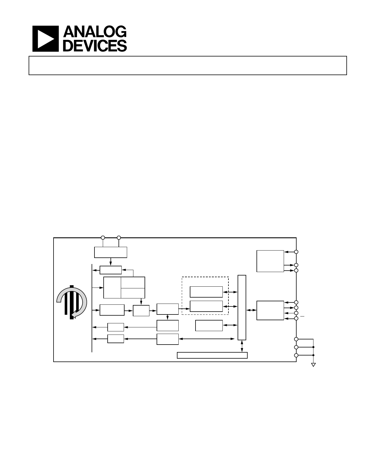
CP5
VX
FUNCTIONAL BLOCK DIAGRAM
HIGH VOLTAGE
GENERATION
www.DataSheet.net/
ADXRS810
Z-AXIS ANGULAR
RATE SENSOR
HV DRIVE
CLOCK
PHASE- DIVIDER
LOCKED
LOOP AMPLITUDE
DETECT
BAND-PASS
FILTER
12-BIT
ADC
Q DAQ
P DAQ
DEMOD
Q FILTER
ST
CONTROL
ALU
DECIMATION
FILTER
TEMPERATURE
CALIBRATION
FAULT
DETECTION
EEPROM
LDO
REGULATOR
PDD
DVDD
AVDD
SPI
INTERFACE
MOSI
MISO
SCLK
CS
DVSS
PSS
AVSS
Figure 1.
Rev. 0
Document Feedback
Information furnished by Analog Devices is believed to be accurate and reliable. However, no
responsibility is assumed by Analog Devices for its use, nor for any infringements of patents or other
rights of third parties that may result from its use. Specifications subject to change without notice. No
license is granted by implication or otherwise under any patent or patent rights of Analog Devices.
Trademarksandregisteredtrademarksarethepropertyoftheirrespectiveowners.
One Technology Way, P.O. Box 9106, Norwood, MA 02062-9106, U.S.A.
Tel: 781.329.4700
©2012 Analog Devices, Inc. All rights reserved.
Technical Support
www.analog.com
Datasheet pdf - http://www.DataSheet4U.co.kr/
1 page 
Data Sheet
ADXRS810
ABSOLUTE MAXIMUM RATINGS
Table 2.
Parameter
Acceleration (Any Axis, Unpowered,
0.5 ms)
Acceleration (Any Axis, Powered, 0.5 ms)
Supply Voltage (PDD)
Output Short-Circuit Duration (Any Pin to
Common)
Operating Temperature Range
Storage Temperature
Rating
2000 g
2000 g
–0.3 V to +6.0 V
Indefinite
−40°C to +125°C
−40°C to +150°C
Stresses above those listed under Absolute Maximum Ratings
may cause permanent damage to the device. This is a stress
rating only; functional operation of the device at these or any
other conditions above those indicated in the operational
section of this specification is not implied. Exposure to absolute
maximum rating conditions for extended periods may affect
device reliability.
THERMAL RESISTANCE
θJA is specified for the worst-case conditions, that is, a device
soldered in a circuit board for surface-mount packages.
Table 3. Thermal Resistance
Package Type
θJA
16-Lead SOIC
191.5
θJC
25
Unit
°C/W
RATE SENSITIVE AXIS
The ADXRS810 is available in a SOIC package. The device
transmits a positive-going LSB count for clockwise rotation
about the axis normal to the package top. Conversely, a
negative-going LSB count is transmitted for counterclockwise
rotation about the Z-axis.
RATE
AXIS
+
16
9
SOIC PACKAGE
Figure 2. RATEOUT Signal Increases with Clockwise Rotation
ESD CAUTION
www.DataSheet.net/
Rev. 0 | Page 5 of 28
Datasheet pdf - http://www.DataSheet4U.co.kr/
5 Page 
Data Sheet
ADXRS810 SIGNAL CHAIN TIMING
The ADXRS810 primary signal chain is in Figure 17. It is the
series of necessary functional circuit blocks through which
the rate data is generated and processed. This sequence of
electromechanical elements determines how quickly the
device is capable of translating an external rate input stimulus
into an SPI word to be sent to the master device. The group
delay, which is a function of the filter characteristic, is the time
required for the output of the low-pass filter to be within 10%
of the external rate input and is seen to be ~4 ms. Additional
delay can be observed due to the timing of SPI transactions and
the population of the rate data into the internal device registers.
This delay is broken down in Figure 17 such that the delay
through each element of the signal chain is presented.
ADXRS810
The transfer function for the rate data low-pass filter (LPF) is
given as
1 Z 64 2
1 Z 1
where:
T 1
1
f0 15.2 kHz (typ)
And the transfer function for the continuous self-test LPF is
given as
1
64 63 Z 1
where:
T 16 16 (typ)
f0 15.2 kHz
PRIMARY SIGNAL CHAIN
4ms
GROUP DELAY
<5µs
DELAY
<5µs
DELAY
<5µs
DELAY
BAND-PASS
FILTER
12-BIT ADC
www.DataSheet.net/
DEMOD
ARITHMETIC
LOGIC UNIT
RATE DATA
LPF
Z-AXIS ANGULAR
RATE SENSOR
CONTINUOUS
SELF-TEST
LPF
<64ms
GROUP DELAY
Figure 17. ADXRS810 Primary Signal Chain and Associated Delays
<2.2ms
DELAY
SPI
TRANSACTION
Rev. 0 | Page 11 of 28
Datasheet pdf - http://www.DataSheet4U.co.kr/
11 Page | ||
| Páginas | Total 28 Páginas | |
| PDF Descargar | [ Datasheet ADXRS810.PDF ] | |
Hoja de datos destacado
| Número de pieza | Descripción | Fabricantes |
| ADXRS810 | Angular Rate Sensor | Analog Devices |
| Número de pieza | Descripción | Fabricantes |
| SLA6805M | High Voltage 3 phase Motor Driver IC. |
Sanken |
| SDC1742 | 12- and 14-Bit Hybrid Synchro / Resolver-to-Digital Converters. |
Analog Devices |
|
DataSheet.es es una pagina web que funciona como un repositorio de manuales o hoja de datos de muchos de los productos más populares, |
| DataSheet.es | 2020 | Privacy Policy | Contacto | Buscar |