|
|
|
PDF EL731 Data sheet ( Hoja de datos )
| Número de pieza | EL731 | |
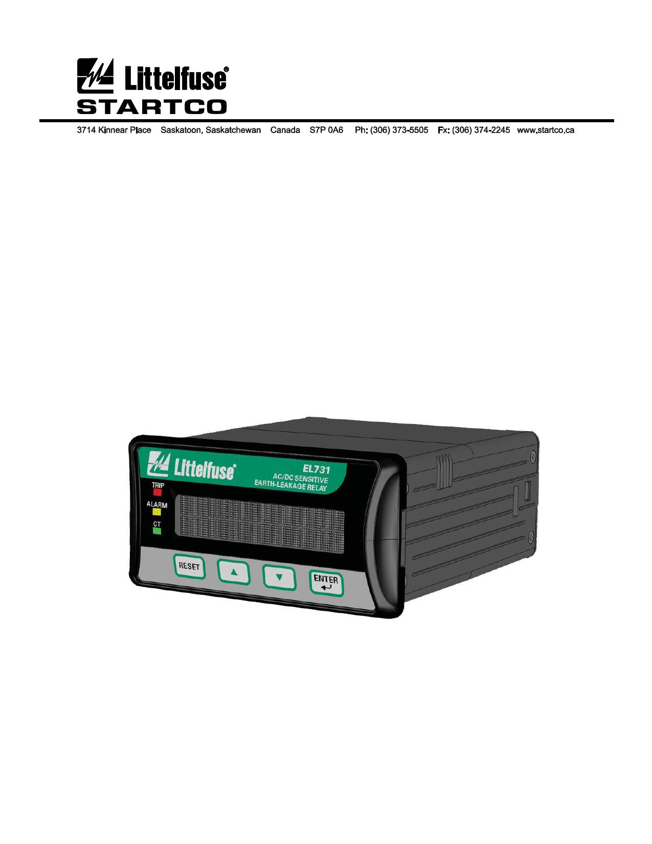
| Descripción | AC/DC SENSITIVE EARTH-LEAKAGE RELAY | |
| Fabricantes | Littelfuse | |
| Logotipo | ||
Hay una vista previa y un enlace de descarga de EL731 (archivo pdf) en la parte inferior de esta página. Total 24 Páginas | ||
|
No Preview Available !
EL731 MANUAL
AC/DC SENSITIVE
EARTH-LEAKAGE RELAY
February 28, 2012
REVISION 2
www.DataSheet.co.kr
Publication: EL731
Document: S95-P401-00001
Printed in Canada.
Copyright © 2012 by Littelfuse Startco
All rights reserved.
Datasheet pdf - http://www.DataSheet4U.net/
1 page 
EL731 AC/DC Sensitive Earth-Leakage Relay
Page 1
Rev. 2
1 INTRODUCTION
1.1 GENERAL
The EL731 is a microprocessor-based earth-leakage
relay for AC, DC, combined AC/DC, and variable-
frequency power circuits supplied by solidly or
resistance-grounded systems that require earth-leakage
detection as low as 30 mA. Earth-leakage metering and
two setting levels (alarm and trip) are provided. A
temperature-sensor input provides metering and
protection for a motor or drive. It is uniquely suited for
sensitive earth-fault protection for adjustable-speed drive
(ASD) circuits that often operate at low speeds.
Settings and configuration selections provide
frequency-response ranges of 0 to 90 Hz, 20 to 90 Hz,
190 to 15,000 Hz, 20 to 15,000 Hz, and 0 to 15,000 Hz.
In each case, alarm- and trip-setting ranges are 30 to
5,000 mA.
Three output relays with normally closed and normally
open contacts can be programmed for various functions
and can be set to operate in the fail-safe or
non-fail-safe mode for undervoltage or shunt-trip
applications.
Additional features include a 2 x 16-character OLED
display, current and temperature metering, programming
and menu-navigation push buttons, password security,
LED trip and alarm indication, auto-reset alarms and
latching trips with front-panel and remote reset, trip
memory, 4- to 20-mA analog output, CT verification
with LED indication, and conformal coated circuits.
Earth-leakage current is sensed by one or two EFCT-
series core-balance zero-sequence current transformers.
The trip level range of the earth-leakage circuit is 30 to
5,000 mA. With two CT’s connected, the EL731
performs independent metering. Trip-time delay is
configurable from instantaneous to two seconds in
millisecond increments.
An optional Ethernet/IP communications interface is
available. Contact the factory for other communication
interface options.
1.2 EL731 FEATURES
AC Ground Overcurrent (50G/51G)
DC Ground Overcurrent (79G)
PTC Overtemperature (49)
RTD Temperature (38, 49)
1.2.1 METERING
Earth-Leakage Current
RTD Temperature or PTC Overtemperature
1.2.2 DATA LOGGING
Trip Counters
Alarm Counters
1.2.3 INPUTS AND OUTPUTS
AC Earth-Leakage Current Transformer (CT2)
AC/DC Earth-leakage Current Transformer (CT1)
Remote Reset Input (one shot operation)
Network Communications (Ethernet/IP – Optional)
4-20-mA Analog Output (programmable, loop
powered)
Temperature-Sensor input (RTD or PTC)
Three output relays, programmable
1.2.4 OPERATOR INTERFACE
2 x 16 OLED display
Display control and programming keys
LED status indication
1.2.5 COMMUNICATIONS INTERFACE
An optional Ethernet/IP interface is available.
An optional update adapter is available for firmware
updates. For ordering information, see Section 7.
www.DataSheet.co.kr
Pub. EL731, February 28, 2012
Datasheet pdf - http://www.DataSheet4U.net/
5 Page 
EL731 AC/DC Sensitive Earth-Leakage Relay
Page 7
Rev. 2
3. OPERATION AND SETUP
3.1 DISPLAY AND INDICATION
The EL731 front panel has three LED’s, a
2-line x 16-character alphanumeric OLED display and
four push buttons to navigate through programming,
status, and system-information menus. The display will
revert to screen-saver mode after 15 minutes. Press any
key to exit the screen saver.
The RESET key is used to clear an earth-leakage-fault
or overtemperature trip. The fault condition must no
longer be present to allow a reset. Continually pressing
the reset key will not prevent a trip.
The up and down arrow keys (▲▼) are used to
navigate the menu system.
The ENTER key is used to select menu items and to
choose settings.
All EL731 settings can be accessed using the EL731
menu system or the optional network communications
interface. In the following sections, menu items and
setup parameters are listed in italics and are shown in the
format displayed on the OLED display.
Menu selection is in the following format:
Menu 1 | Sub Menu 1 | Sub Menu 2 | Sub Menu 3 |…
When browsing a selection list, an asterisk (*)
indicates the active item. If the intent is to exit the list
and not to change the setting, press ENTER on the
selection that has the asterisk (*).
If the item is a string (or numerical) input and no
change is desired, press ENTER until the display returns
to the menu system. To exit a main-menu list, scroll and
select Exit.
A menu map is provided in Appendix A at the end of
this manual.
3.1.1 FRONT-PANEL LED INDICATION
3.1.1.1 TRIP
The red LED labeled TRIP indicates a trip condition
when flashing. Refer to Table 1 for applicable flash
codes.
TABLE 1: TRIP FLASH CODES
FAULT
CODES
Overcurrent CT1
1 short, 1 long
Overcurrent CT2
2 short, 1 long
CT1 Detection
3 short, 1 long
CT2 Detection
4 short, 1 long
NVRAM Error
5 short, 1 long
CT1 Calibration Failure
6 short, 1 long
RTD/PTC Trip
7 short, 1 long
User Test
8 short, 1 long
Watchdog
Fast flash
Trip cause is also available on the OLED display
through the | Messages | State menu item.
3.1.1.2 CT STATUS
The green LED labeled CT will flash during CT1
calibration. It will be solid green when CT connections are
correct, and off when a CT is connected incorrectly.
3.1.1.3 ALARM
The yellow LED labeled ALARM will be on when
measured current is above an alarm setting.
3.1.2 ETHERNET/IP MODULE LED INDICATION
There are three LED’s on the optional
AC700-CUA-03 Ethernet/IP communications module.
Their purpose and indication are shown in Tables 2, 3,
and 4.
TABLE 2: NETWORK STATUS LED (NS)
LED STATE
DESCRIPTION
Off No power or no IP address
Green
On-line, one or more
connections established
Green, flashing
On-line, no connections
established
Red Duplicate IP address,
FATAL error
Red, flashing
One or more connections
timed out
TABLE 3: MODULE STATUS LED (MS)
LED STATE
DESCRIPTION
Off No power
Green
Controlled by a Scanner in
Run State
Green, flashing
Not configured, or Scanner
in Idle state
R e dwww.DataSheet.co.kr
Major fault (EXCEPTION-
state, FATAL error)
Red, flashing
Recoverable fault(s)
TABLE 4: LINK/ACTIVITY LED (LINK)
LED STATE
DESCRIPTION
Off No link, no activity
Green
Link established
Green, flickering
Activity
Pub. EL731, February 28, 2012
Datasheet pdf - http://www.DataSheet4U.net/
11 Page | ||
| Páginas | Total 24 Páginas | |
| PDF Descargar | [ Datasheet EL731.PDF ] | |
Hoja de datos destacado
| Número de pieza | Descripción | Fabricantes |
| EL7300 | highly integrated single chip solution for the Flat Panel Display applications | Etron Technology Inc. |
| EL7300Q-110 | highly integrated single chip solution for the Flat Panel Display applications | Etron Technology Inc. |
| EL7300Q-140 | highly integrated single chip solution for the Flat Panel Display applications | Etron Technology Inc. |
| EL7300Q-160 | highly integrated single chip solution for the Flat Panel Display applications | Etron Technology Inc. |
| Número de pieza | Descripción | Fabricantes |
| SLA6805M | High Voltage 3 phase Motor Driver IC. |
Sanken |
| SDC1742 | 12- and 14-Bit Hybrid Synchro / Resolver-to-Digital Converters. |
Analog Devices |
|
DataSheet.es es una pagina web que funciona como un repositorio de manuales o hoja de datos de muchos de los productos más populares, |
| DataSheet.es | 2020 | Privacy Policy | Contacto | Buscar |