|
|
|
PDF ACD2204 Data sheet ( Hoja de datos )
| Número de pieza | ACD2204 | |
| Descripción | CATV/TV/Video Downconverter | |
| Fabricantes | ANADIGICS | |
| Logotipo | ||
Hay una vista previa y un enlace de descarga de ACD2204 (archivo pdf) en la parte inferior de esta página. Total 20 Páginas | ||
|
No Preview Available !
FEATURES
• Integrated Downconverter
• Integrated Dual Synthesizer
• 256 QAM Compatibility
• Single +5 V Power Supply Operation
• Low Noise Figure: 8 dB
• High Conversion Gain: 31 dB
• Low Distortion: -53 dBc
• Three-Wire Interface
• Small Size
• -40 °C to +85 °C
APPLICATIONS
• Set Top Boxes
• CATV Video Tuners
• Digital TV Tuners
• CATV Data Tuners
• Cable Modems
ACD2204
CATV/TV/Video Downconverter
with Dual Synthesizer
PRELIMINARY DATA SHEET - Rev 1.0
S8 Package
28 Pin SSOP
PRODUCT DESCRIPTION
The ACD2204 uses both GaAs and Si technology
to provide the downconverter and dual synthesizer
functions in a double conversion tuner gain block,
local oscillator, balanced mixer, IF Amplifier, and
dual synthesizer. The specifications meet the
requirements of CATV/TV/Video and Cable Modem
Data applications. The ACD2204 is supplied in a 28
lead SSOP package and requires a single +5 V
supply voltage. The IC is well suited for applications
where small size, low cost, low auxiliary parts count,
and no-compromise performance is important. It
provides for cost reduction by lowering the
component and packaged IC count and decreasing
the amount of labor-intensive production alignment
steps, while significantly improving performance
and reliability.
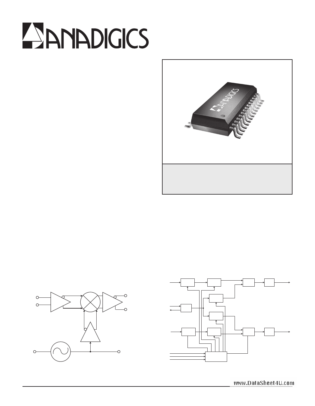
RF IN+
RF IN-
www.DataSheeLVtoG4wAUNo.ciseom
Mixer
V IF +IF OUT-
V IF +IF OUT+
Phase Splitter
RF D
RF2: 64/65
Prescaler
REF IN
REF OU T
Oscillato r
RF U
RF1: 64/65
Prescaler
18 Bit RF2
N C ounter
15 Bit RF2
R C ounter
15 Bit RF1
R C ounter
18 Bit RF1
N C ounter
RF2
Phase
Detector
RF 2
Charge
Pump
CP D
RF1
Phase
Detector
RF1
Charge
Pump
CP U
T CKT
OSC OUT
Figure 1: Downconverter Block Diagram
Clock
Data
Enabl e
22 Bi t
Data Registar
Figure 2: Dual Synthesizer Block Diagram
04/2003
1 page 
ACD2204
Table 4: Electrical Specifications - Downconverter Section
(TA = 25 °C, VDD = +5 VDC, RFIN = 1087 MHz, IFOUT = 45 MHz)
PARAMETER
MIN TYP MAX UNIT
Conversion Gain (1)
28 31
-
dB
SSB Noise Figure (1)
- 8 10 dB
Cross Modulation (1), (2), (4)
- -59 -
dBc
3rd Order Intermodulation Distortion
(IMD3) (1), (3), (4)
- - -53 dBc
2-Tone 3rd Order Input Intercept Point
(IIP3) (1), (3), (4)
-10
-
- dBm
LO Phase Noise (@ 10 KHz Offset) (1) -
-90 -85.5 dBc/Hz
LO Output Power (pin 24) (1)
- -5 - dBm
Spurious @ IF Output
LO Signals and Harmonics
- -10 - dBm
Beats Within Output Channel
- -70 -
dBc
Other Beats from 2 to 200 MHz - -50 - dBm
Other Spurious
- -10 - dBm
IF Supply Current (pin 27 & 28) (1), (4) - 110 -
mA
Osc, Phase Splitter and Mixer Supply
Current (pin 25)
-
70
-
mA
Power Consumption
- 900 -
mW
Notes:
(1) As measured in ANADIGICS test fixture.
(2) Two tones: 1085 and 1091 MHz, -40 dBm each, 1091 MHz tone AM-modulated 99% at 15 kHz.
(3) Two tones: 1085 and 1091 MHz, -30 dBm each.
(4) R1 = 0 Ohms
Table 5: Electrical Specifications - Synthesizer Section
(TA = +25 °C, VDD = +5 VDC)
PARAMETER
MIN TYP MAX UNIT
COMMENTS
Prescalar Input Sensitivity
Upconverter: RFU (pin 16) (1)
Downconverter: RFD (pin 19) (2)
(over operating frequency)
-7 - +20 dBm
-13 - +20
Reference Oscillator Sensitivity (pin 13)
-
0.5
-
wwCwh.aDrgaetaPShuemept4OUu.ctopmut Current (3)
SINK
SOURCE
- 1.25 -
- -1.25 -
Vp-p
mA
Supply Current
- 35 50 mA
Power Consumption
Notes:
(1) Measured at 250 kHz comparison frequency.
(2) Measured at 62.5 kHz comparison frequency.
(3) CPU and CPD = Vcc/2.
-
165 250
mW
PRELIMINARY DATA SHEET - Rev 1.0
04/2003
5
5 Page 
ACD2204
For the up converter, the 4 MHz crystal oscillator frequency and the 250 KHz phase detector comparison
frequency are used to yield RPLL1 = 4 MHz / 250 KHz = 16, and so the bit values for the up converter R counter
are RPLL1 = 000000000010000.
Calculation of Main Divider Values
The values for the A and B counters are determined by the desired VCO output frequency for the local
oscillator and the phase detector comparison frequency:
N = fVCO / f PD
B = trunc(N / P)
A = N - (B x P)
The down converter local oscillator frequency will be 1087.75 MHz - 45.75 MHz = 1042 MHz in this example.
The main divider ratio for the down converter, then, is NPLL2 = 1042 MHz / 62.5 KHz = 16672. Since P = 64 in the
ACD2204, BPLL2 = trunc(16672 / 64) = 260, and APLL2 = 16672 - (260 x 64) = 32. These results give bit values
of BPLL2 = 00100000100 and APLL2 = 0100000 for the B and A counters.
The up converter local oscillator frequency will be 499.25 MHz + 1087.75 MHz = 1587 MHz in this example.
Therefore, NPLL1 = 1587 MHz / 250 KHz = 6348, BPLL1 = trunc(6348 / 64) = 99, and APLL1 = 6348 - (99 x 64) = 12.
These results give bit values of BPLL1 = 00001100011 and APLL1 = 0001100 for the B and A counters.
Phase Detector Polarity
Assuming the VCO for the up converter has a negative slope, the phase detector polarity for PLL1 should be
negative, and D1PLL1 = 1. If the VCO for the down converter has a positive slope, the phase detector polarity for
PLL2 should be positive, and D1PLL2 = 0.
In summary, for this example, the four register programming words are shown in Tables 16 and 17:
MSB
Table 16: PLL1 and PLL2 Reference Divider Register Bits
for Synthesizer Programming Example
LSB
22 21 20 19 18 17 16 15 14 13 12 11 10 9 8 7 6 5 4 3 2 1
Program
Mode
Main Divider B Counter
Main Divider A Counter Select
C C B B B B B B B B B B BAAAAAAA S S
2 1 11 10 9 8 7 6 5 4 3 2 1 7 6 5 4 3 2 1 2 1
0 0 0 0 1 0 0 0 0 0 1 0 0 0 100000 0 1
0 0 0 0 0 0 1 1 0 0 0 1 1000 1100 1 1
MSB
Table 17: PLL1 and PLL2 Main Divider Register Bits
for Synthesizer Programming Example
LSB
ww2w2.Da2ta1Sh2ee0t4U1.9com18 17 16 15 14 13 12 11 10 9 8 7 6 5 4 3 2 1
Program Mode
Reference Divider R Counter
Select
DDDDDRRRRRRRRRRRRRRR S S
5 4 3 2 1 15 14 13 12 11 10 9 8 7 6 5 4 3 2 1 2 1
0000 100000000 100000000
000000000000000 10000 10
PRELIMINARY DATA SHEET - Rev 1.0
04/2003
11
11 Page | ||
| Páginas | Total 20 Páginas | |
| PDF Descargar | [ Datasheet ACD2204.PDF ] | |
Hoja de datos destacado
| Número de pieza | Descripción | Fabricantes |
| ACD2202 | CATV/TV/Video Downconverter with Dual Synthesizer | ANADIGICS Inc |
| ACD2202S8P0 | CATV/TV/Video Downconverter with Dual Synthesizer | ANADIGICS Inc |
| ACD2202S8P1 | CATV/TV/Video Downconverter with Dual Synthesizer | ANADIGICS Inc |
| ACD2203 | CATV/TV/Video Downconverter with Dual Synthesizer | ANADIGICS |
| Número de pieza | Descripción | Fabricantes |
| SLA6805M | High Voltage 3 phase Motor Driver IC. |
Sanken |
| SDC1742 | 12- and 14-Bit Hybrid Synchro / Resolver-to-Digital Converters. |
Analog Devices |
|
DataSheet.es es una pagina web que funciona como un repositorio de manuales o hoja de datos de muchos de los productos más populares, |
| DataSheet.es | 2020 | Privacy Policy | Contacto | Buscar |