|
|
|
PDF ADT7310 Data sheet ( Hoja de datos )
| Número de pieza | ADT7310 | |
| Descripción | system specific power supply IC | |
| Fabricantes | ADTech | |
| Logotipo | ||
Hay una vista previa y un enlace de descarga de ADT7310 (archivo pdf) en la parte inferior de esta página. Total 15 Páginas | ||
|
No Preview Available !
ADT7310
General Description
The ADT7310 is system specific power supply IC
that is suitable for color CCD camera.
Other features include over-current protection,
thermal shutdown. It reduces design complexity
and external component count.
ADT7310
YYWW
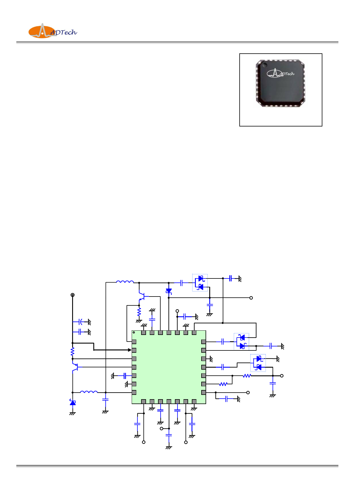
Package outline of the ADT7310
Features
Applications
• Input voltage range : 4.75V to 18V
• Color CCD camera
• Multiple output voltage channel available
• CCTV camera
- 2 channel 3.3V outputs , 200mA / 60mA max.
• distributed power system
- 1.8V output , 40mA max.
(3.3V / 1.8V / 5V / 15V / -7V)
- 5V boost converter output , 100mA max.
- 15V output , 10mA max.
- Externally adjustable negative voltage output (-7V typical)
• Power-on-reset output & power sequence
• Protection : thermal shutdown , over-current protection
• Small size(5x5 mm2 body) and thermally enhanced 28 Pin MLF Package
Typical Application Circuit
VIN
C100
L2
QN1
Rs2
U1
CF1
D2
1.8V
C2
CL7
CL1
5V
C200
U2
CF2
CL2
Rs1
QP1
C10
L1 VIN2
C1
D1
CL4
U0
(ADT7310)
C30 Ct
RBO C40
CL5
U3
CF3
Rn2
CL6
Rn1 CL3
15V
3.3VD
3.3VA
* This specifications are subject to be changed without notice
-7V
Oct. 17. 2008 / Rev. 0.0
1/15 http://www.ad-tech.co.kr
www.DataSheet.in
1 page 
ADT7310
Absolute Maximum Ratings
Parameter
Symbol
Min.
Typ.
Max.
Power supply voltage
Power dissipation (Ta=70℃) *1
VIN
PDmax
-
-
- 20
- 2.2
Storage temperature
TSTG
-65
- +150
Junction temperature
TJmax
-
- +150
Thermal resistance
ΘJA - 35 -
*1 derate 35℃/W above +70℃.
Stresses beyond those listed under “Absolute Maximum Ratings” may cause permanent damage to
the device. These are stress ratings only, and functional operation of the device at these or any other
conditions beyond those indicated in the operational sections of the specifications is not implied.
Exposure to absolute maximum rating conditions for extended periods may affect device reliability.
Unit
V
W
℃
℃
℃/W
Operating Ratings
Parameter
Symbol
Min.
Typ.
Max.
Unit
Power supply voltage
VIN 4.75
12
18
Operating temperature
TOPR
-20
-
+85
Junction temperature
Max. power dissipation (Ta=70℃)*1
TJ -
PD -
- +125
- 1.5
*1 This spec. indicates that junction temperature of the device is under 125℃. In specific applications,
this is recommended under this power dissipation specification.
V
℃
℃
W
Electrical Characteristics (Ta = 25℃ , VIN = 12V , unless otherwise noted.)
Parameter
Condition
Min Typ Max
Basic Function
Operating supply voltage
-
4.75 12
18
ICC with no load
Power on reset
Tdelay
VOH
VIN=12V, w/o loading
VIN=12V , C30 =22㎋
-
5.0 8.0 11.0
- 8.5 -
3.0 3.3 3.6
Over-temperature
protection
On Junction temperature at OT enable
Off Junction temperature at OT release
- 140 -
- 110 -
Efficiency
Switching frequency
VIN=12V , max. load current
Continuous mode , Ct=13㎊
Continuous mode , Ct=18㎊
- 58 -
400 500 600
300 400 500
Buck Converter (+3.7V output)
Output voltage (VIN2)
VIN=12V
3.5 3.7 3.9
Unit
V
㎃
㎳
V
℃
℃
%
㎑
㎑
V
Note
Note1
Note2
* This specifications are subject to be changed without notice
Oct. 17. 2008 / Rev. 0.0
5/15 http://www.ad-tech.co.kr
www.DataSheet.in
5 Page 
ADT7310
Application Hints (continued)
OUTPUT CAPACITOR SELECTION
Use a 10uF, 10V ceramic capacitor. Use X7R or X5R types,
where IOUTMAX : maximum load current
L : min. inductor value including worst case tolerance
do not use Y5V.
The output filter capacitor smoothes out current flow from the
inductor to the load, helps maintain a steady output voltage du-
CHARGE PUMP CONSIDERATIONS
ring transient load changes and reduces output voltage ripple.
These capacitors must be selected with sufficient capacitance
and sufficiently low ESR to perform these functions.
The output voltage ripple is caused by the charging and disch-
arging of the output capacitor and also due to its ESR and can
be calculated as :
Voltage peak-to-peak ripple due to capacitance can be express-
ed as follows
VPP-C = IRIPPLE / (4 * f * C)
where IRIPPLE : Average to peak inductor current
f : Minimum switching frequency
Voltage peak-to-peak ripple due to ESR can be expressed as
follows
VPP-ESR = (2 * IRIPPLE) * RESR
Because these two components are out of phase the rms value
can be used to get an approximate value of peak-to-peak
ripple.
Voltage peak-to-peak ripple, root mean squared can be expre-
DOUBLER / INVERTER CAPACITOR SELECTION
The flying capacitor (CF*) transfers charge from the its input
power supply to the output. A polarized capacitor (tantalum,
aluminum electrolytic, etc.) must not be used here, as the
capacitor will be reverse biased upon start-up of the ADT7310.
The size of the flying capacitor and its ESR affect output cur-
rent capability and ripple characteristic. In this applications,
a 1uF, X7R or X5R type ceramic capacitor is recommended
for the flying capacitor.
The load capacitor (CL1,2,3) of the charge pump plays an imp-
ortant part in determining the characteristics of the doubler
output. The ESR of the output load capacitor affects charge
pump output resistance, which plays a role in determining
output current capability. Both output capacitance and ESR
affect output voltage ripple. For these reasons, a low value
ESR capacitor is recommended.
ssed as follows
VPP-RMS = √ (VPP-C2 + VPP-ESR2)
Note that the output voltage ripple is dependent on the inductor
current ripple and the ESR of the output capacitor. The ESR
is frequency dependent (as well as temperature dependent),
make sure the value used for calculations is at the switching
frequency of the part.
BOOST CONSIDERATIONS
INDUCTOR SELECTION
As previously mentioned from the inductor selection at the
buck converter, inductor at the boost converter also needs to be
considered two factors when choosing an inductor;
the inductor should not saturate, and the inductor current ripple
INPUT CAPACITOR SELECTION
The ADT7310 uses 10uF, 25V tantalum capacitor for input
capacitor. Use a mix of input bypass capacitors to control the
voltage overshoot. Use ceramic capacitor for the high frequen-
cy decoupling and tantalum capacitor to supply the required
rms input current. Place the input capacitor as close as possible
to the VIN pin of the device. The input filter capacitor supplies
current to the PNP switching transistor of the converter in the
first half of each cycle and reduces voltage ripple imposed on
is small enough to achieve the desired output voltage ripple.
By the property of cascading boost converter from buck conv-
erter, its inductor saturation current is lower than the that of the
buck converter. In this application, the same 47uH adopted and
is sufficient. Boost converter drives both its load current and
the following charge pump converters for generating +15V and
-7V. For proper operation at the power up time this inductor
needs more saturation current than its total load current requir-
ed.
the input power source. The input current ripple can be calcul-
ated as :
IRMS = IOUTMAX ∗
1−
VOUT
VIN
∗
⎜⎜⎝⎛
VOUT
VIN
+
r2
12
⎟⎟⎠⎞
r = (VIN − VOUT ) ∗ VOUT
L ∗ f ∗ IOUTMAX ∗ VIN
OUTPUT CAPACITOR SELECTION
Use a 10uF, 10V ceramic capacitor. Use X7R or X5R types,
do not use Y5V. (the same component as buck converter)
* This specifications are subject to be changed without notice
Oct. 17. 2008 / Rev. 0.0
11/15
http://www.ad-tech.co.kr
www.DataSheet.in
11 Page | ||
| Páginas | Total 15 Páginas | |
| PDF Descargar | [ Datasheet ADT7310.PDF ] | |
Hoja de datos destacado
| Número de pieza | Descripción | Fabricantes |
| ADT7310 | 16-Bit Digital SPI Temperature Sensor | Analog Devices |
| ADT7310 | system specific power supply IC | ADTech |
| ADT7311 | 16-Bit Digital SPI Temperature Sensor | Analog Devices |
| ADT7312 | Digital SPI Temperature Sensor | Analog Devices |
| Número de pieza | Descripción | Fabricantes |
| SLA6805M | High Voltage 3 phase Motor Driver IC. |
Sanken |
| SDC1742 | 12- and 14-Bit Hybrid Synchro / Resolver-to-Digital Converters. |
Analog Devices |
|
DataSheet.es es una pagina web que funciona como un repositorio de manuales o hoja de datos de muchos de los productos más populares, |
| DataSheet.es | 2020 | Privacy Policy | Contacto | Buscar |