|
|
|
PDF D2-45057 Data sheet ( Hoja de datos )
| Número de pieza | D2-45057 | |
| Descripción | (D2-45057 / D2-45157) Intelligent Digital Amplifier PWM Controller and Audio Processor | |
| Fabricantes | Intersil Corporation | |
| Logotipo | ||
Hay una vista previa y un enlace de descarga de D2-45057 (archivo pdf) en la parte inferior de esta página. Total 30 Páginas | ||
|
No Preview Available !
Intelligent Digital Amplifier PWM Controller and
Audio Processor
D2-45057, D2-45157
The D2-45057 and D2-45157 devices are complete
System-on-Chip (SoC) Class-D digital audio amplifiers.
Combining high performance integrated Power Stages
along with an optimized Audio Processor feature set and
PWM Controller, these devices offer a complete,
powerful, and very cost effective audio solution for high
volume and cost-critical products.
This 4th generation Digital Audio Engine (DAE-4P)™
device combines extensive integrated Digital Signal
Processor (DSP) audio processing with amplifier control,
for a complete audio solution. Its ease of integration into
the existing system processor provides complete support
for all system product and amplifier functions.
The four configurable Power Stages operate as four
separate Half-Bridge outputs, as two Full-Bridge outputs,
or in combinations of Half-Bridge plus Full-Bridge,
providing flexible loudspeaker drive solutions. Separate
PWM outputs provide additional combinations to drive
headphone, or line level stereo and subwoofer outputs.
Related Literature
• DAE-4/DAE-4P Register API Specification
• DAE-4P Evaluation Kit Guides
Features
• All Digital Class-D Amplifier and Controller with
Integrated Digital Signal Processing (DSP)
• Four Integrated Power Stages Supporting
- 2 Channels, Bridged
- 4 Channels, Half-Bridge
- 2 Channels, Half-Bridge, plus 1 Channel Bridged
• Output Power (Bridged)
- 25W (8Ω, <1% THD); 30W (8Ω, <10% THD)
• Fully Programmable Digital Signal Processing (DSP)
- Up to 5 Programmable Audio Signal Path Channels
- Programmable Equalizers, Filters, Mixers, Limiters
• Includes D2Audio™ SoundSuite™ and
SRS WOW/HD™ Audio Enhancement Algorithms
• I2S and S/PDIF™ Digital Audio Inputs
• Asynchronous Sample Rate Converters;
Sample Rates from 32kHz up to 192kHz
• Wide 9V to 26V Power Stage HV Supply Range, plus
Internally-Generated Gate Drive Supply
• Temperature and Undervoltage Monitoring
and Individual Channel Protection
Applications
• PC/Multimedia Speakers
• Digital TV Audio Systems
• Portable Device Docking Stations
• Powered Speaker Systems
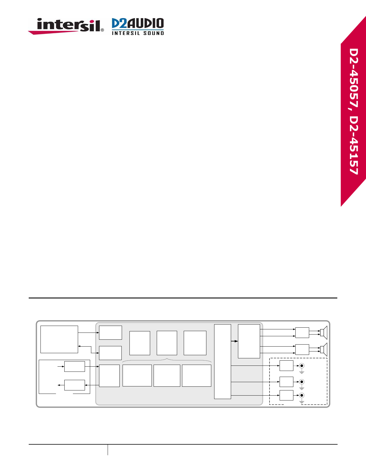
Typical System Implementation
SoC
System
Controller(s)
I2S
I2C
Optical/
Coax IN
S/PDIF
Buffer
Optical/
Coax OUT
S/PDIF
Buffer
(Optional)
Digital
Audio
Interface
I2C
Control
S/PDIF
Digital I/O
Interface
2 Channel
Sample
Rate
Converter
24 Bit
Digital
Signal
Processor
5 Channel
PWM
Engine
D2Audio®
Audio Canvas™
Processing
D2Audio®
SoundSuite™
3rd Party
ENHANCEMENTS
(SRS WOW/HD®)
PWM
Output
Drive
D2-45x57-QR
DAE-4P™ Intelligent Digital Power Amplifier and Audio Processor
Amplifier
Output
MOSFETS
Amplifier Output 1
Amplifier Output 2
Amplifier Output 3
Amplifier Output 4
Output
Filter
Output
Filter
PWM Output
Filter
Subwoofer
Line Out
PWM Output
Filter
PWM Output
Filter
(Optional)
Stereo
Line Out
OR
Headphone
Out
SYSTEM APPLICATION IMPLEMENTING 2X FULL-BRIDGE LOUDSPEAKER OUTPUTS PLUS 3 LINE-LEVEL OUTPUTS
July 29, 2010
FN6785.0
www.DataSheet.in
1 CAUTION: These devices are sensitive to electrostatic discharge; follow proper IC Handling Procedures.
1-888-INTERSIL or 1-888-468-3774 | Intersil (and design) is a registered trademark of Intersil Americas Inc.
Copyright Intersil Americas Inc. 2010. All Rights Reserved
All other trademarks mentioned are the property of their respective owners.
1 page 
D2-45057, D2-45157
Electrical Specifications TA = +25°C, HVDD[A:D]/VDDHV = 24V, CVDD = PLLVDD = 1.8V ±5%, RVDD = PWMVDD = 3.3V
±10%. All grounds at 0.0V. All voltages referenced to ground. PLL at 294.912MHz, OSC at 24.576MHz, core running at
147.456MHz with typical audio data traffic. (Continued)
PARAMETER
TEST
CONDITIONS
SYMBOL
MIN
TYP MAX UNIT
Analog Supply Pins (PLL)
PLLVDD
1.7
1.8 1.9 V
Active Current
- 10 - mA
Power-Down Current
(Note 10)
- 5 - mA
CRYSTAL OSCILLATOR
Crystal Frequency (Fundamental Mode Crystal)
Xo 20 24.576 25 MHz
Duty Cycle
Dt 40 - 60 %
Start-up Time (Start-up Time is Oscillator Enabled
(with Valid Supply) to Stable Oscillation)
tSTART
-
5 20 ms
PLL
VCO Frequency
PLL Lock Time from any Input Change
FVCO
240 294.912 300 MHz
- 3 - ms
1.8V POWER-ON RESET
Reset Enabled Voltage Level
POR Minimum Output Pulse Width
1.8V BROWNOUT DETECTION
VEN
tDIS
0.95
-
1.1 1.3 V
5 - µs
Detect Level
1.4 1.5 1.7 V
Pulse Width Rejection
Minimum Output Pulse Width
3.3V (PWMVDD) BROWNOUT DETECTION
tBOD1
tO1
-
-
100 - ns
20 - ns
Detect Level
2.5 2.7 2.9 V
Pulse Width Rejection
Minimum Output Pulse Width
GATE DRIVE INTERNAL +5V BROWN-OUT DETECTION
tBOD3
tO3
-
-
100 - ns
20 - ns
Gate Drive Supply Undervoltage Threshold
- 4.5 - V
Gate Drive Supply Undervoltage Threshold Hysteresis
- 200 - mV
Gate Drive Supply Undervoltage Threshold Glitch
Rejection
- 50 - ns
PROTECTION DETECT
High Voltage (+VDDHV) Undervoltage Protection
- 7 9V
Overcurrent Trip Threshold
- 4 -A
Overcurrent De-glitch
- 2.5 - ns
Short-Circuit Current Limit (Peak)
- 8 -A
Overcurrent Response Time
- 20 - ns
Thermal Shut-Down (Power Stages)
- 140 - °C
Thermal Shut-Down Hysteresis (Power Stages)
- 30 - °C
NOTES:
8. All input pins except XTALI.
9. Input leakage applies to all pins except XTALO.
10. Power-down is with device in reset and clocks stopped.
www.DataSheet.in
5
FN6785.0
July 29, 2010
5 Page 
D2-45057, D2-45157
Pin Description (Continued)
PIN
VOLTAGE
NAME
LEVEL
PIN (Note 13) TYPE (V)
DESCRIPTION
24 nERROR/ I/O
CFG0
3.3 Output configuration selection input, and nERROR output. Upon device reset, pin operates
as input, using application-installed pull-up or pull-down connection to pin to specify one of
4 amplifier configurations. Upon internal D2-45057, D2-45157 firmware execution, pin
becomes output, providing active-low output drive when amplifier protection monitoring
detects an error condition. When operating as output, provides 4mA drive strength. (Note:
This pin may also be referenced as “PSCURR” on some reference designs. Function is
identical regardless of name.)
25 PSSYNC/ I/O
CFG1
3.3 Output configuration selection input, and power supply sync output. Upon device reset, pin
operates as input, using application-installed pull-up or pull-down connection to pin to
specify one of 4 amplifier configurations. Upon internal D2-45057, D2-45157 firmware
execution, pin becomes output, providing synchronizing signal to on-board power supply
circuits. When operating as output, provides 4mA drive strength. Note: This pin may also
be referenced as “PSTEMP” on some reference designs. Function is identical regardless of
name.
26 PROTECT0 I/O
3.3 PWM protection input. Input has hysteresis. Protection monitoring functionality of pin is
controlled by internal D2-45057, D2-45157 firmware, and dependent on which of the 4
amplifier configurations is enabled.
27 PROTECT1 I/O
3.3 PWM protection input. Input has hysteresis. Protection monitoring functionality of pin is
controlled by internal D2-45057, D2-45157 firmware, and dependent on which of the 4
amplifier configurations is enabled.
28 PROTECT2 I/O
29 nERROR0 O
30 nERROR1 O
3.3 PWM protection input. Input has hysteresis. Protection monitoring functionality of pin is
controlled by internal D2-45057, D2-45157 firmware, and dependent on which of the 4
amplifier configurations is enabled.
3.3 Overcurrent protection output, channel A output stage. Open drain 16mA driver, with internal
100kΩ (approx.) pull-up. Pulls low when active from overcurrent detection of output stage.
3.3 Overcurrent protection output, channel B output stage. Open drain 16mA driver, with internal
100kΩ (approx.) pull-up. Pulls low when active from overcurrent detection of output stage.
31 nERROR2 O
3.3 Overcurrent protection output, channel C output stage. Open drain 16mA driver, with internal
100kΩ (approx.) pull-up. Pulls low when active from overcurrent detection of output stage.
32 nERROR3 O
3.3 Overcurrent protection output, channel D output stage. Open drain 16mA driver, with internal
100kΩ (approx.) pull-up. Pulls low when active from overcurrent detection of output stage.
33 HVDDD P
34 HGNDD GND
35 OUTD
36 HSBSD
O
I
HV Output stage D high voltage supply power. A separate power pin connection is provided for
each of the output stages. All of the HVDD[A:D] pins and the VDDHV pin connect to the
system “HV” power source.
HV Output stage D high voltage supply ground. A separate ground pin connection is provided
for each of the output stages. All of the HGND[A:D] pins connect to system “HV” power
ground (also see Note 15).
HV PWM power amplifier output, channel D.
HV High-side boot strap input, output channel D. Capacitor couples to OUTD amplifier output.
37 HSBSC
I
HV High-side boot strap input, output channel C. Capacitor couples to OUTC amplifier output.
38 OUTC
O
HV PWM power amplifier output, channel C.
39 HGNDC GND
HV Output stage C high voltage supply ground. A separate ground pin connection is provided
for each of the output stages. All of the HGND[A:D] pins connect to system “HV” power
ground (also see Note 15).
40 HVDDC
P
41 SUBOUT O
42 DNC
-
HV Output stage C high voltage supply power. A separate power pin connection is provided for
each of the output stages. All of the HVDD[A:D] pins and the VDDHV pin connect to the
system “HV” power source.
3.3 “Subwoofer” channel PWM output, with 16mA drive strength. Connects to filter network for
supplying line-level analog output to subwoofer.
- Do not connect to this pin.
www.DataSheet.in
11
FN6785.0
July 29, 2010
11 Page | ||
| Páginas | Total 30 Páginas | |
| PDF Descargar | [ Datasheet D2-45057.PDF ] | |
Hoja de datos destacado
| Número de pieza | Descripción | Fabricantes |
| D2-45057 | (D2-45057 / D2-45157) Intelligent Digital Amplifier PWM Controller and Audio Processor | Intersil Corporation |
| Número de pieza | Descripción | Fabricantes |
| SLA6805M | High Voltage 3 phase Motor Driver IC. |
Sanken |
| SDC1742 | 12- and 14-Bit Hybrid Synchro / Resolver-to-Digital Converters. |
Analog Devices |
|
DataSheet.es es una pagina web que funciona como un repositorio de manuales o hoja de datos de muchos de los productos más populares, |
| DataSheet.es | 2020 | Privacy Policy | Contacto | Buscar |