|
|
|
PDF ECMF04-4AMX12 Data sheet ( Hoja de datos )
| Número de pieza | ECMF04-4AMX12 | |
| Descripción | EMI Filtering And Signal Conditioning Common mode filter | |
| Fabricantes | ST Microelectronics | |
| Logotipo | ||
Hay una vista previa y un enlace de descarga de ECMF04-4AMX12 (archivo pdf) en la parte inferior de esta página. Total 14 Páginas | ||
|
No Preview Available !
DataSheet.in
ECMF04-4AMX12
Common mode filter with ESD protection for
MIPI D-PHY and MDDI interface
Features
■ Very large differential bandwidth > 6 GHz
■ High common mode attenuation:
– -34 dB at 900 MHz
– -20 dB between 800 MHz and 2.2 GHz
■ Very low PCB space consumption
■ Thin package: 0.6 mm max
■ Lead-free package
■ High reduction of parasitic elements through
integration
Applications
■ Mobile phones
■ Notebook, laptop
■ Portable devices
■ PND
Description
The ECMF04-4AMX12 is a highly integrated
common mode filter designed to suppress
EMI/RFI common mode noise on high speed
differential serial buses like MIPI D-PHY or MDDI.
The ECMF04-4AMX12 can protect and filter 2
differential lines.
Micro QFN-12L 3.3 mm x 1.5 mm
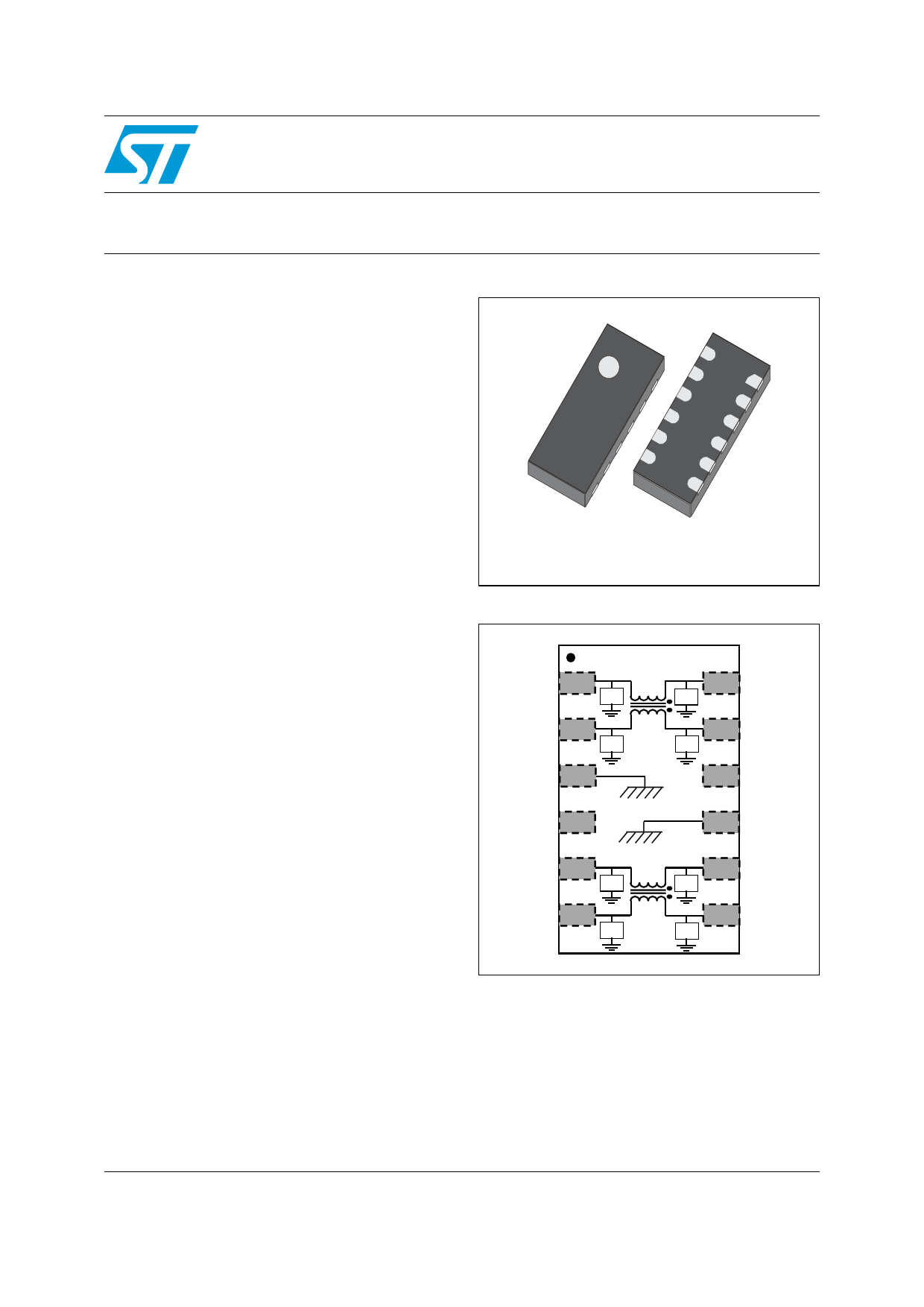
Figure 1. Pin configuration and schematics
D1+
ESD
D1-
ESD
GND1
NC
D0+
ESD
D0 -
ESD
D1+
ESD
D1 -
ESD
NC
GND0
D0+
ESD
D0-
ESD
August 2010
Doc ID 17793 Rev 1
1/14
www.st.com
14
1 page 
DataSheet.in
ECMF04-4AMX12
Figure 11. MIPI D-PHY low power mode test setup
Characteristics
Generator Agilent 81110
Pattern mode, F=10MHz,
modulation RZ, 50Ω output
Oscilloscope Lecroy
7300A, 1MΩ input
CMF
Figure 12. Low power pulse response - see Figure 11 for test setup
500 mV/div
Pulse: 50 ns, tr = tf = 5 ns
500 mV/div
200 ns/div
200 ns/div
Doc ID 17793 Rev 1
5/14
5 Page 
DataSheet.in
ECMF04-4AMX12
Recommendation on PCB assembly
5.2 Solder paste
1. Use halide-free flux, qualification ROL0 according to ANSI/J-STD-004.
2. “No clean” solder paste recommended.
3. Offers a high tack force to resist component displacement during PCB movement.
4. Use solder paste with fine particles: powder particle size 20-45 µm.
5.3 Placement
1. Manual positioning is not recommended.
2. It is recommended to use the lead recognition capabilities of the placement system, not
the outline centering.
3. Standard tolerance of ± 0.05 mm is recommended.
4. 3.5 N placement force is recommended. Too much placement force can lead to
squeezed out solder paste and cause solder joints to short. Too low placement force
can lead to insufficient contact between package and solder paste that could cause
open solder joints or badly centered packages.
5. To improve the package placement accuracy, a bottom side optical control should be
performed with a high resolution tool.
6. For assembly, a perfect supporting of the PCB (all the more on flexible PCB) is
recommended during solder paste printing, pick and place and reflow soldering by
using optimized tools.
5.4 PCB design preference
1. To control the solder paste amount, the closed via is recommended instead of open
vias.
2. The position of tracks and open vias in the solder area should be well balanced. The
symmetrical layout is recommended, in case any tilt phenomena caused by
asymmetrical solder paste amount due to the solder flow away.
Doc ID 17793 Rev 1
11/14
11 Page | ||
| Páginas | Total 14 Páginas | |
| PDF Descargar | [ Datasheet ECMF04-4AMX12.PDF ] | |
Hoja de datos destacado
| Número de pieza | Descripción | Fabricantes |
| ECMF04-4AMX12 | EMI Filtering And Signal Conditioning Common mode filter | ST Microelectronics |
| Número de pieza | Descripción | Fabricantes |
| SLA6805M | High Voltage 3 phase Motor Driver IC. |
Sanken |
| SDC1742 | 12- and 14-Bit Hybrid Synchro / Resolver-to-Digital Converters. |
Analog Devices |
|
DataSheet.es es una pagina web que funciona como un repositorio de manuales o hoja de datos de muchos de los productos más populares, |
| DataSheet.es | 2020 | Privacy Policy | Contacto | Buscar |