|
|
|
PDF ADM1086 Data sheet ( Hoja de datos )
| Número de pieza | ADM1086 | |
| Descripción | Simple Sequencers in 6-Lead SC70 | |
| Fabricantes | Analog Devices | |
| Logotipo | ||
Hay una vista previa y un enlace de descarga de ADM1086 (archivo pdf) en la parte inferior de esta página. Total 16 Páginas | ||
|
No Preview Available !
Data Sheet
Simple Sequencers® in 6-Lead SC70
ADM1085/ADM1086/ADM1087
FEATURES
Provide programmable time delays between enable
signals
Can be cascaded with power modules for multiple
supply sequencing
Power supply monitoring from 0.6 V
Output stages
High voltage (up to 22 V) open-drain output
(ADM1085/ADM1087)
Push-pull output (ADM1086)
Capacitor-adjustable time delays
High voltage (up to 22 V) enable and VIN inputs
Low power consumption (15 μA)
Specified over –40°C to +125°C temperature range
6-lead SC70 package
APPLICATIONS
Desktop/notebook computers, servers
Low power portable equipment
Routers
Base stations
Line cards
Graphics cards
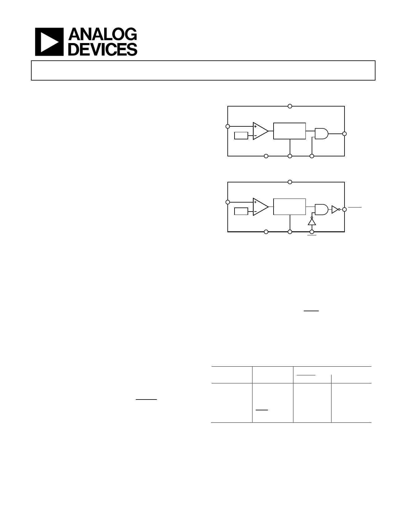
FUNCTIONAL BLOCK DIAGRAMS
VCC
ADM1085/ADM1086
VIN
0.6V
CAPACITOR
ADJUSTABLE
DELAY
ENOUT
GND
CEXT
ENIN
ADM1087
VIN
0.6V
VCC
CAPACITOR
ADJUSTABLE
DELAY
ENOUT
GND
CEXT
ENIN
Figure 1.
GENERAL DESCRIPTION
The ADM1085/ADM1086/ADM1087 are simple sequencing
circuits that provide a time delay between the enabling of
voltage regulators and/or dc-dc converters at power-up in
multiple supply systems. When the output voltage of the first
power module reaches a preset threshold, a time delay is
initiated before an enable signal allows subsequent regulators to
power up. Any number of these devices can be cascaded with
regulators to allow sequencing of multiple power supplies.
Threshold levels can be set with a pair of external resistors in a
voltage divider configuration. With appropriate resistor values,
the threshold can be adjusted to monitor voltages as low as 0.6 V.
The ADM1086 has a push-pull output stage, with active high
(ENOUT). The ADM1085 has an active-high (ENOUT) logic
output; the ADM1087 has an active-low (ENOUT) output. Both
the ADM1085 and ADM1087 have open-drain output stages
that can be pulled up to voltage levels as high as 22 V through
an external resistor. This level-shifting property ensures
compatibility with enable input logic levels of different
regulators and converters.
All four models have a dedicated enable input pin that allows
the output signal to the regulator to be controlled externally.
This is an active high input (ENIN) for the ADM1085 and
ADM1086, and an active low input (ENIN) for the ADM1087.
The Simple Sequencers are specified over the extended
−40°C to +125°C temperature range. With low current
consumption of 15 μA (typical) and 6-lead SC70 packaging,
the parts are suitable for low-power portable applications.
Table 1. Selection Table
Part No.
Enable Input
Output Stage
ENOUT
ENOUT
ADM1085
ENIN
Open-drain
ADM1086
ENIN
Push-pull
ADM1087
ENIN
Open-drain
Rev. B
Document Feedback
Information furnished by Analog Devices is believed to be accurate and reliable. However, no
responsibility is assumed by Analog Devices for its use, nor for any infringements of patents or other
rights of third parties that may result from its use. Specifications subject to change without notice. No
license is granted by implication or otherwise under any patent or patent rights of Analog Devices.
Trademarksandregisteredtrademarksarethepropertyoftheirrespectiveowners.
One Technology Way, P.O. Box 9106, Norwood, MA 02062-9106, U.S.A.
Tel: 781.329.4700 ©2004–2014 Analog Devices, Inc. All rights reserved.
Technical Support
www.analog.com
1 page 
Data Sheet
PIN CONFIGURATION AND FUNCTION DESCRIPTIONS
ADM1085/ADM1086/ADM1087
ENIN/ENIN
1
ADM1085/
ADM1086/
6
VCC
GND 2 ADM1087 5 CEXT
VIN 3 TOP VIEW 4 ENOUT/ENOUT
(Not to Scale)
Figure 2. Pin Configuration
Table 4. Pin Function Descriptions
Pin No. Mnemonic
Description
1
ENIN, ENIN
Enable Input. Controls the status of the enable output. Active high for ADM1085/ADM1086. Active low for
ADM1087.
2 GND
Ground.
3 VIN
Input for the Monitored Voltage Signal. Can be biased via a voltage divider resistor network to customize the
effective input threshold. Can precisely monitor an analog power supply output signal and detect when it has
powered up. The voltage applied at this pin is compared with a 0.6 V on-chip reference. With this reference,
digital signals with various logic level thresholds can also be detected.
4 ENOUT, ENOUT Enable Output. Asserted when the voltage at VIN is above VTH_RISING and the time delay has elapsed, provided
that the enable input is asserted. Active high for the ADM1085/ADM1086. Active low for the ADM1087.
5 CEXT
External Capacitor Pin. The capacitance on this pin determines the time delay on the enable output. The delay
is seen only when the voltage at VIN rises past VTH_RISING, and not when it falls below VTH_FALLING.
6 VCC
Power Supply.
Rev. B | Page 5 of 16
5 Page 
Data Sheet
APPLICATION INFORMATION
SEQUENCING CIRCUITS
The ADM1085/ADM1086/ADM1087 are compatible with
voltage regulators and dc-to-dc converters that have active high
or active low enable or shutdown inputs, with a choice of open-
drain or push-pull output stages. Figure 23 to Figure 25
illustrate how each of the ADM1085/ADM1086/ADM1087
simple sequencers can be used in multiple-supply systems,
depending on which regulators are used and which output
stage is preferred.
ADM1085/ADM1086/ADM1087
In Figure 23, three ADM1085s are used to sequence four
supplies on power-up. Separate capacitors on the CEXT pins
determine the time delays between enabling of the 3.3 V, 2.5 V,
1.8 V, and 1.2 V supplies. Because the dc-to-dc converters and
ADM1085s are connected in a cascade, and the output of any
converter is dependent on that of the previous one, an external
controller can disable all four supplies simultaneously by
disabling the first dc-to-dc converter in the chain.
For power-down sequencing, an external controller dictates
when the supplies are switched off by accessing the ENIN
inputs individually.
12V
3.3V
3.3V
3.3V
IN
EN DC/DC OUT
3.3V
3.3V
IN
EN DC/DC OUT
2.5V
3.3V
IN
EN DC/DC OUT
1.8V
3.3V
IN
EN DC/DC OUT 1.2V
ENABLE
CONTROL
VCC
VIN ENOUT
ADM1085
ENIN CEXT
VCC
VIN ENOUT
ADM1085
ENIN CEXT
VCC
VIN ENOUT
ADM1085
ENIN CEXT
12V
3.3V
2.5V
1.8V
1.2V
tEN1
tEN2
tEN3
EXTERNAL
DISABLE
Figure 23. Typical ADM1085 Application Circuit
Rev. B | Page 11 of 16
11 Page | ||
| Páginas | Total 16 Páginas | |
| PDF Descargar | [ Datasheet ADM1086.PDF ] | |
Hoja de datos destacado
| Número de pieza | Descripción | Fabricantes |
| ADM1085 | Simple Sequencers in 6-Lead SC70 | Analog Devices |
| ADM1086 | Simple Sequencers in 6-Lead SC70 | Analog Devices |
| ADM1087 | Simple Sequencers in 6-Lead SC70 | Analog Devices |
| ADM1088 | Simple Sequencers in 6-Lead SC70 | Analog Devices |
| Número de pieza | Descripción | Fabricantes |
| SLA6805M | High Voltage 3 phase Motor Driver IC. |
Sanken |
| SDC1742 | 12- and 14-Bit Hybrid Synchro / Resolver-to-Digital Converters. |
Analog Devices |
|
DataSheet.es es una pagina web que funciona como un repositorio de manuales o hoja de datos de muchos de los productos más populares, |
| DataSheet.es | 2020 | Privacy Policy | Contacto | Buscar |