|
|
|
PDF ACT6360 Data sheet ( Hoja de datos )
| Número de pieza | ACT6360 | |
| Descripción | 40V Step-Up WLED Bias Supplies | |
| Fabricantes | Active-Semi | |
| Logotipo | ||
Hay una vista previa y un enlace de descarga de ACT6360 (archivo pdf) en la parte inferior de esta página. Total 9 Páginas | ||
|
No Preview Available !
ACT6360www.DataSheet4U.com
Rev0, 23-May-08
High-Efficiency, 40V Step-Up WLED Bias Supplies
FEATURES
• High-Efficiency DC/DC WLED Bias Supply
• Internal 40V, 0.55Ω Power MOSFET
• Up to 10 WLEDs per String
• 1000mA Peak Current
• Supports Analog and PWM LED Dimming
• Integrated Over-Voltage Protection (OVP)
• Thermal Shutdown
• Cycle-by-Cycle Over Current Protection
• Tiny SOT23-6 Package
APPLICATIONS
• TFT LCD Displays
• Smart Phones
• Portable Media Players
• GPS/Personal Navigation Devices
GENERAL DESCRIPTION
The ACT6360 step-up DC/DC converter drives
white LEDs with an externally programmable con-
stant current. This device features an integrated,
40V power MOSFET that is capable of driving up to
ten white LEDs in series, providing inherent current
matching for uniform brightness. WLED brightness
adjustment is easily achieved via simple external
circuitry, which accepts either a PWM or an analog
dimming control signal.
The ACT6360 features a variety of protection cir-
cuits, including integrated over voltage protection
(OVP), cycle-by-cycle current limiting, and thermal
shutdown protection circuitry.
The ACT6360 has a 1000mA current limit, and is
available in a small 6-pin SOT23-6 package.
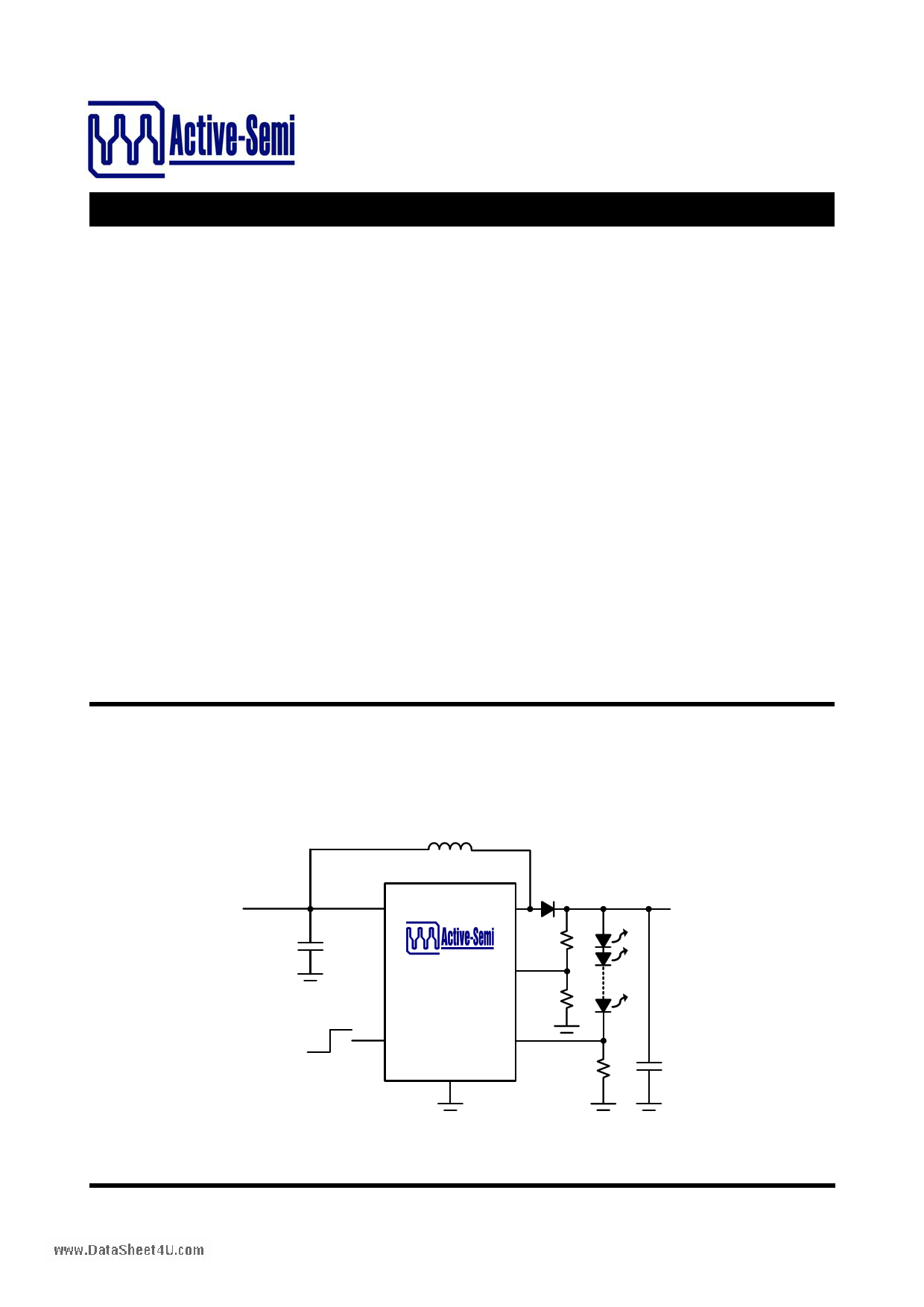
SIMPLIFIED APPLICATION CIRCUIT
VIN
CIN
ON
OFF
L1
Up to
D1 10 WLEDs
IN SW
ACT6360 OV
ROV2
ROV1
VOUT
EN FB
G
RFB
COUT
Innovative PowerTM
- 1 - www.active-semi.com
Copyright © 2008 Active-Semi, Inc.
1 page 
FUNCTIONAL BLOCK DIAGRAM
IN
EN
ENABLE
CIRCUIT
UVLO
ACT6360www.DataSheet4U.com
Rev0, 23-May-08
DRIVER
SW
THERMAL
SHUTDOWN
CONTROL
LOGIC
OV COMPARATOR
OV +
1.21V
-
MAXIMUM
ON TIME
BANDGAP
REFERENCE
MINIMUM
OFF TIME
-
ACT6360
ERROR
+ 0.29V
COMPARATOR
G
FB
Control Scheme
The ACT6360 uses a minimum off-time, current-
mode control scheme to achieve excellent perform-
ance under high duty-cycle operating conditions.
This control scheme initiates a switching cycle only
when needed to maintain output voltage regulation,
resulting in very high efficiency operation.
During each switching cycle, the N-channel power
MOSFET turns on, increasing the inductor current.
The switching cycle terminates when either the in-
ductor current reaches the current limit (1000mA) or
when the cycle lasts longer than the maximum on-
time of 4µs. Once the MOSFET turns off, it remains
off for at least the minimum off-time of 320ns, then
another switching begins when the error compara-
tor detects that the output is falling out of regulation
again.
Over Voltage Protection
The ACT6360 includes internal over-voltage protec-
tion circuitry that monitors the OV pin voltage. Over-
voltage protection is critical when one of the LEDs
in the LED string fails as an open circuit. When this
happens the feedback voltage drops to zero, and
the control switches at maximum on time causing
the output voltage to keep rising until it exceeds the
maximum voltage rating of the power MOSFET.
The over-voltage protection circuit detects this con-
dition and switching ceases if the voltage at the OV
pin reaches 1.21V.
To set the maximum output voltage, connect a re-
sistor divider from the output node to G, with center
tap at OV, and select the two resistors with the fol-
lowing equation:
ROV 2
=
ROV1
×
⎢⎣⎡⎜⎝⎛1V.2O1VV
⎟⎞
⎠
−1⎥⎤
⎦
where VOV is the over voltage detection threshold,
ROV1 is the resistor between OV and G, and ROV2 is
the resistor from the output to the OV pin. As a first
estimate, the OV threshold can often be set to 4V
times the number of LEDs in the string.
Setting the LED Current
The LED current is programmed by appropriate se-
lection of the feedback resistor RFB connected be-
tween FB and G. To set the LED current, choose
the resistor according to the equation:
R FB
= VFB
I LED
where VFB is the FB feedback voltage (typically
290mV at VEN = 3.3V) and ILED is the desired maxi-
mum LED current.
Innovative PowerTM
- 5 - www.active-semi.com
Copyright © 2008 Active-Semi, Inc.
5 Page | ||
| Páginas | Total 9 Páginas | |
| PDF Descargar | [ Datasheet ACT6360.PDF ] | |
Hoja de datos destacado
| Número de pieza | Descripción | Fabricantes |
| ACT6360 | 40V Step-Up WLED Bias Supplies | Active-Semi |
| Número de pieza | Descripción | Fabricantes |
| SLA6805M | High Voltage 3 phase Motor Driver IC. |
Sanken |
| SDC1742 | 12- and 14-Bit Hybrid Synchro / Resolver-to-Digital Converters. |
Analog Devices |
|
DataSheet.es es una pagina web que funciona como un repositorio de manuales o hoja de datos de muchos de los productos más populares, |
| DataSheet.es | 2020 | Privacy Policy | Contacto | Buscar |