|
|
|
PDF CAT5140 Data sheet ( Hoja de datos )
| Número de pieza | CAT5140 | |
| Descripción | Single Channel 256 Tap Digital Potentiometer | |
| Fabricantes | ON Semiconductor | |
| Logotipo | ||
Hay una vista previa y un enlace de descarga de CAT5140 (archivo pdf) en la parte inferior de esta página. Total 10 Páginas | ||
|
No Preview Available !
CAT5140
Single Channel 256 Tap
Digital Potentiometer (POT)
with Integrated EEPROM
and I2C Control
The CAT5140 is a single channel non-volatile 256-tap digital POT.
This digital POT is comprised of a series of equal value resistor
elements connected between two externally accessible end points. The
tap points between each resistive element can be selectively connected
to the wiper output via internal CMOS switches forming a linear taper
electronic potentiometer.
The CAT5140 contains a volatile wiper register (WR) and an 8-bit
non-volatile EEPROM for wiper position and 5 additional
non-volatile registers for general purpose data storage. Programming
of the registers is controlled via I2C interface. On power up, the wiper
position is reset to the most recent value stored in the non-volatile
memory register (IVR).
The CAT5140 is available in an Pb free, RoHS compliant 8-lead
MSOP package, and operates over the industrial temperature range of
−40C to +85C.
Features
400 kHz I2C Compatible Interface
256 Position Linear Taper Potentiometer
End-to-End Resistance = 50 kW / 100 kW
TCR = 100 ppm/C (typical)
Standby Current = 2 mA (max)
Typical Wiper Resistance = 70 W @ 3.3 V
Operating Voltage = 2.5 V to 5.5 V
6 Registers 8-bit Non-volatile EEPROM
2,000,000 Data Write Stores
100 Year Data Retention
8-lead MSOP Package
NiPdAu Plating
These Devices are Pb-Free and are RoHS Compliant
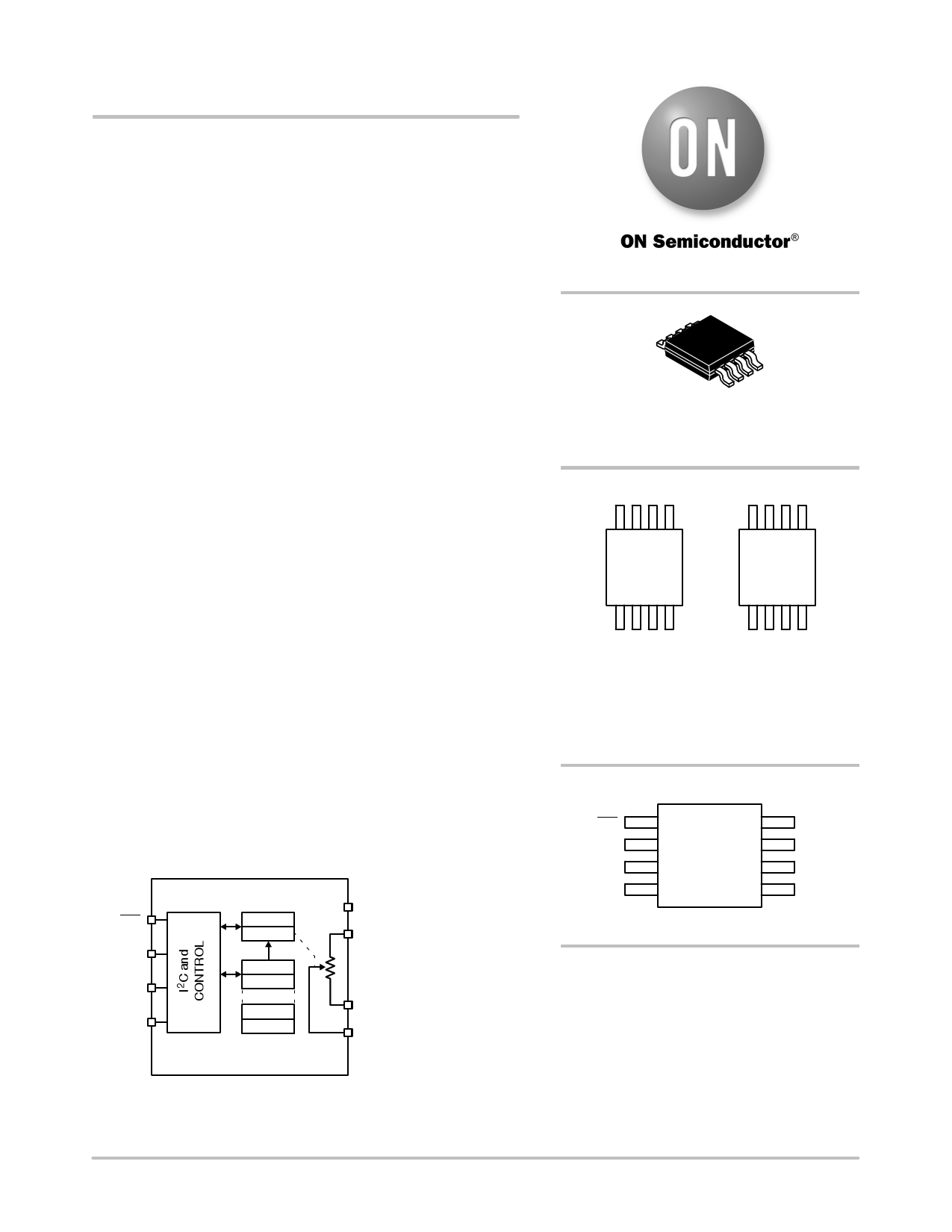
WP
SCL
SDA
GND
Volatile
ACR
WIPER
IVR
GP
GP
GP
Non−Volatile
VCC
RH
RL
RW
Figure 1. Functional Block Diagram
http://onsemi.com
MSOP−8 3x3
Z SUFFIX
CASE 846AD
MARKING DIAGRAM
ABUT
YMX
ABTJ
YMX
11
ABUT = 100 kW Resistance
ABTJ = 50 kW Resistance
Y = Production Year
Y = (Last Digit)
M = Production Month
M = (1 − 9, A, B, C)
X = Production Revision
WP
SCL
SDA
GND
PIN CONNECTIONS
1
(Top View)
VCC
RH
RL
RW
ORDERING INFORMATION
See detailed ordering and shipping information in the package
dimensions section on page 2 of this data sheet.
Semiconductor Components Industries, LLC, 2013
July, 2013 − Rev. 4
1
Publication Order Number:
CAT5140/D
1 page 
CAT5140
SCL
SDA
Start
Condition
Figure 2. Start and STOP Timing
Stop
Condition
tF
SCL
tSU:STA
SDA IN
SDA OUT
tLOW
tHIGH
tHD:STA
tHD:DAT
tAA
tR
tSU:DAT
tDH
Figure 3. Bus Timing
SCL from
Master
Bus Release Delay (Transmitter)
18
9
tSU:STO
tBUF
Bus Release
Delay (Receiver)
Data Output
from Transmitter
Data Output
from Receiver
Start
ACK Delay ( tAA)
Figure 4. Acknowledge Timing
ACK Setup ( tSU:DAT)
Start
SCL
CLK1
Stop
tHD:STO, tHD:STO:NV
SDA IN
WP
tSU:WP
Figure 5. WP Timing
tHD:WP
http://onsemi.com
5
5 Page | ||
| Páginas | Total 10 Páginas | |
| PDF Descargar | [ Datasheet CAT5140.PDF ] | |
Hoja de datos destacado
| Número de pieza | Descripción | Fabricantes |
| CAT514 | 8-Bit Quad Digital POT | Catalyst Semiconductor |
| CAT5140 | Single Channel 256 Tap Digital Potentiometer | ON Semiconductor |
| Número de pieza | Descripción | Fabricantes |
| SLA6805M | High Voltage 3 phase Motor Driver IC. |
Sanken |
| SDC1742 | 12- and 14-Bit Hybrid Synchro / Resolver-to-Digital Converters. |
Analog Devices |
|
DataSheet.es es una pagina web que funciona como un repositorio de manuales o hoja de datos de muchos de los productos más populares, |
| DataSheet.es | 2020 | Privacy Policy | Contacto | Buscar |