|
|
|
PDF ADIS16130 Data sheet ( Hoja de datos )
| Número de pieza | ADIS16130 | |
| Descripción | High-Precision Angular Rate Sensor | |
| Fabricantes | Analog Devices | |
| Logotipo | ||
Hay una vista previa y un enlace de descarga de ADIS16130 (archivo pdf) en la parte inferior de esta página. Total 16 Páginas | ||
|
No Preview Available !
Data Sheet
Digital Output, High Precision
Angular Rate Sensor
ADIS16130
FEATURES
GENERAL DESCRIPTION
Low noise density: 0.0125o/sec/√Hz
Industry-standard serial peripheral interface (SPI)
24-bit digital resolution
Dynamic range: ±250o/sec
Z-axis, yaw rate response
Bandwidth, adjustable: 300 Hz
Turn-on time: 35 ms
Digital self-test
High vibration rejection
High shock survivability
Embedded temperature sensor output
Precision voltage reference output
5 V single-supply operation
−40°C to +85°C
APPLICATIONS
Guidance and control
Instrumentation
Inertial measurement units (IMU)
Platform stabilization
Navigation
The ADIS16130 is a low noise, digital output angular rate sensor
(gyroscope) that provides an output response over the complete
dynamic range of ±250o/sec.
Its industry-standard serial interface and register structure provide
a simple interface that is supported by most MCU, DSP, and FPGA
platforms.
By implementing a unique design, the device provides superior
stability over variations in temperature, voltage, linear acceleration,
vibration, and next-level assembly. In addition, the surface-micro-
machining technology used to manufacture the device is the
same high volume BiMOS process used by Analog Devices, Inc.,
for its high reliability automotive sensor products.
Features include a temperature output that provides critical
information for system-level calibrations and a digital self-test
feature that exercises the mechanical structure of the sensor and
enables system-level diagnostics.
The package configuration is a 36 mm × 44 mm × 16 mm
module with a standard 24-lead connector interface.
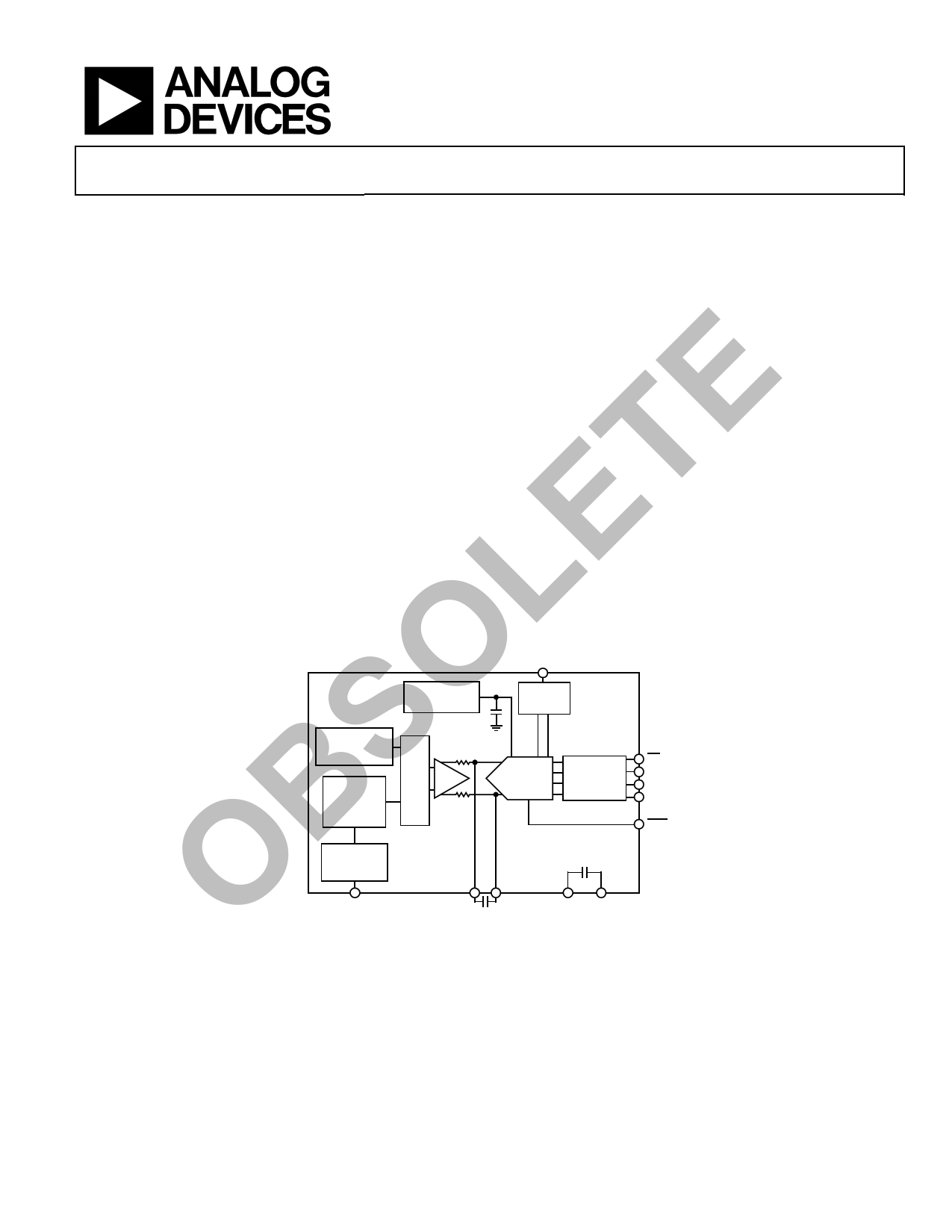
FUNCTIONAL BLOCK DIAGRAM
SYNC
ADIS16130
REFERENCE
SYNC
TEMPERATURE
SENSOR
MEMS
ANGULAR
RATE
SENSOR
2:1
MUX
SELF-TEST
24-BIT
Σ-∆ ADC
SERIAL
INTERFACE
CS
SCLK
SDI
SDO
RDY
ST
ROA1
ROA2
VCC GND
Figure 1.
Rev. C
Information furnished by Analog Devices is believed to be accurate and reliable. However, no
responsibility is assumed by Analog Devices for its use, nor for any infringements of patents or other
rights of third parties that may result from its use. Specifications subject to change without notice. No
license is granted by implication or otherwise under any patent or patent rights of Analog Devices.
Trademarksandregisteredtrademarksarethepropertyoftheirrespectiveowners.
One Technology Way, P.O. Box 9106, Norwood, MA 02062-9106, U.S.A.
Tel: 781.329.4700
www.analog.com
Fax: 781.461.3113 ©2008–2011 Analog Devices, Inc. All rights reserved.
1 page 
Data Sheet
CS
SCLK
SDI
CS
SCLK
SDO
t11 t14
t12
t13
MSB
t15
Figure 2. Input Timing for Write Operation
t4 t6
t5 t7
t5A
MSB
Figure 3. Output Timing for Read Operation
ISINK (800µA AT DVDD = 5V
100µA AT DVDD = 3V)
TO OUTPUT
PIN
50pF
1.6V
ISOURCE (200µA AT DVDD = 5V
100µA AT DVDD = 3V)
Figure 4. Load Circuit for Access Time and Bus Relinquish Time
ADIS16130
t16
LSB
t8
t9
LSB
Rev. C | Page 5 of 16
5 Page 
Data Sheet
ADIS16130
CONTROL REGISTERS
Table 10. Register Descriptions
Name
Address
COM
0x00
IOP 0x01
0x02 to 0x07
RATEDATA
0x08
TEMPDATA
0x0A
0x10 to 0x22
RATECS
0x28
TEMPCS
0x2A
RATECONV
0x30
TEMPCONV
0x32
0x33 to 0x37
MODE
0x38
Type
W
R/W
R
R
R/W
R/W
R/W
R/W
R/W
CONTROL REGISTER DETAILS
Table 11. COM Register Bit Assignments
Bit Description
[7] 0
[6] 1 = read;
0 = write
[5:0] Register address
Purpose
Facilitate communications in the SPI port (see Table 11)
Data-ready and synchronization controls (see Table 12)
Reserved
Gyroscope output, rate of rotation
Temperature output
Reserved
Gyroscope channel setup (see Table 13)
Temperature channel setup (see Table 14)
Gyroscope conversion time control (see Table 15)
Temperature conversion time control (see Table 15)
Reserved
Resolution mode control (see Table 16)
Table 14. TEMPCS Register Bit Assignments
Bit Description
[7:4] 0000
[3] 1 = channel enable;
0 = channel disable
[2:0] 010
Table 12. IOP Register Bit Assignments
Bit Description
[7:4] 0011
[3] 1 = data-ready signal low when unread data on all channels;
0 = data-ready signal low when unread data on one channel
[2:1] 00
[0] 0 = synchronization disabled;
1 = synchronization enabled
Table 13. RATECS Register Bit Assignments
Bit Description
[7:4] 0000
[3] 1 = channel enable;
0 = channel disable
[2:0] 010
Table 15. RATECONV/TEMPCONV Bit Assignments
Bit Description
[7:0] 00000101
Table 16. MODE Register Bit Assignments
Bit Description
[7:2] 001000
[1] 1 = 24-bit resolution;
0 = 16-bit resolution
[0] 0
Rev. C | Page 11 of 16
11 Page | ||
| Páginas | Total 16 Páginas | |
| PDF Descargar | [ Datasheet ADIS16130.PDF ] | |
Hoja de datos destacado
| Número de pieza | Descripción | Fabricantes |
| ADIS16130 | High-Precision Angular Rate Sensor | Analog Devices |
| ADIS16133 | Precision Angular Rate Sensor | Analog Devices |
| ADIS16135 | +-300 /Sec Precision Angular Rate Sensor | Analog Devices |
| ADIS16136 | Precision Angular Rate Sensor | Analog Devices |
| Número de pieza | Descripción | Fabricantes |
| SLA6805M | High Voltage 3 phase Motor Driver IC. |
Sanken |
| SDC1742 | 12- and 14-Bit Hybrid Synchro / Resolver-to-Digital Converters. |
Analog Devices |
|
DataSheet.es es una pagina web que funciona como un repositorio de manuales o hoja de datos de muchos de los productos más populares, |
| DataSheet.es | 2020 | Privacy Policy | Contacto | Buscar |