|
|
|
PDF A1171 Data sheet ( Hoja de datos )
| Número de pieza | A1171 | |
| Descripción | Micropower Ultrasensitive Hall Effect Switch | |
| Fabricantes | Allegro MicroSystems | |
| Logotipo | ||
Hay una vista previa y un enlace de descarga de A1171 (archivo pdf) en la parte inferior de esta página. Total 10 Páginas | ||
|
No Preview Available !
A1171
Micropower Ultrasensitive Hall Effect Switch
Features and Benefits
▪ 1.65 to 3.5 V battery operation
▪ Low supply current
▪ High sensitivity, BOP typically 30 G (3.0 mT)
▪ Operation with either north or south pole
▪ Configurable unipolar or omnipolar magnetic sensing
▪ Complementary, push-pull outputs
▪ Chopper stabilized
▫ Superior temperature stability
▫ Extremely low switchpoint drift
▫ Insensitive to physical stress
▪ Solid state reliability
▪ Small size
Package: 6 pin DFN/MLP (suffix EW)
Description
The A1171 integrated circuit is an ultrasensitive, Hall effect
switch with latched digital outputs and either unipolar or
omnipolar magnetic actuation. It features operation at low
supply currents and voltages, making it ideal for battery-
operated electronics. The low operating supply voltage,
1.65 to 3.5 V, and unique clocking algorithm assist in reducing
the average operating power consumption. For example, the
power requirement is less than 15 μW with a 2.75 V supply.
Unlike more traditional Hall effect switches, the A1171 allows
the user to configure how the device is magnetically actuated.
Under default conditions the device activates output switching
with either a north or south polarity magnetic field of sufficient
strength. The magnetic actuation can be set via an external
selection pin to operate in a unipolar mode, switching only on
a north or south polarity but not both. Furthermore, the output
of the A1171 can be configured to switch either off or on in the
absence of any significant magnetic field. Lastly, the A1171
has two push-pull output structures.
This polarity-independence, as well as the minimal power
requirements, allows theA1171 to easily replace reed switches,
Not to scale
Continued on the next page…
VDD
1171-DS, Rev. 5
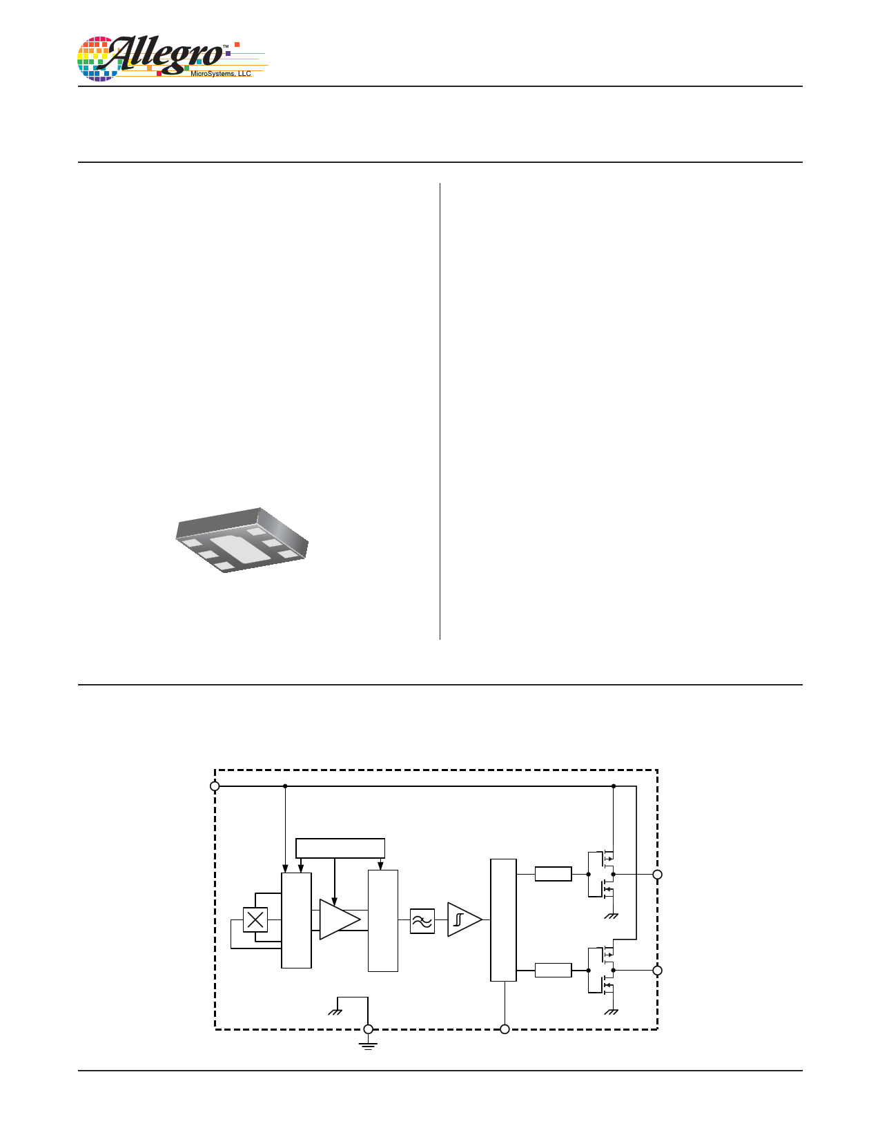
Functional Block Diagram
Clock / Logic
Amp
Low-Pass
Filter
Latch
Latch
GND
SELECT
VOUTPS
VOUTPN
1 page 
A1171
Micropower Ultrasensitive Hall Effect Switch
Functional Description
Low Average Power
Internal timing circuitry activates the IC for a short period of
time, tAwake, and deactivates it for the remainder of the period
(tPeriod). A short awake state duration allows stabilization prior
to the sampling and data-latching on the falling edge of the tim-
ing pulse. The output during the sleep state is latched in the last
sampled state. The supply current is not affected by the output
state.
IDD(EN)
Awake
tPeriod
Sleep
IDD(DIS)
0
Sample and Output Latched
Operation
The VOUTPS output switches low (turns on) when the magnetic
field received at the Hall element in the A1171 exceeds the oper-
ate point, BOPS (or is less than BOPN). After turn-on, the output
voltage is VOUT(SAT). The output transistor is capable of sinking
current up to the short circuit current limit, IOM. When the mag-
netic field is reduced below the release point, BRPS (or increased
above BRPN), the device output switches high (turns off). The
pull-up transistor brings the output voltage to VOUT(HIGH).
VOUTPN operates with the opposite output polarity. That is, the
output is low (on) in the absence of a magnetic field. The output
goes high (turns off) when sufficient field, or either north or
south polarity, is presented to the device.
The difference between the magnetic operate and release points
is the hysteresis, BHYS , of the device. This built-in hysteresis
allows clean switching of the output even in the presence of
external mechanical vibration and electrical noise.
Powering-on the device in a hysteresis region, between BOPX
and BRPX, allows an indeterminate output state. The correct state
is attained after the first excursion beyond BOPX or BRPX.
(A) VOUTPS
(B) VOUTPN
V+ V+
VOUT(HIGH)
VOUT(HIGH)
0
B–
0
VOUT(SAT)
B+
0
B–
0
VOUT(SAT)
B+
BHYS
BHYS
BHYS
BHYS
Figure 1. Switching Behavior of Omnipolar Switches. On the horizontal axis, the B+ direction indicates increasing south polarity magnet-
ic field strength, and the B– direction indicates decreasing south polarity field strength (including the case of increasing north polarity).
This output switching profile applies when the SELECT line is allowed to float, selecting omnipolar operation.
Allegro MicroSystems, LLC
115 Northeast Cutoff
Worcester, Massachusetts 01615-0036 U.S.A.
1.508.853.5000; www.allegromicro.com
5
5 Page | ||
| Páginas | Total 10 Páginas | |
| PDF Descargar | [ Datasheet A1171.PDF ] | |
Hoja de datos destacado
| Número de pieza | Descripción | Fabricantes |
| A1171 | Micropower Ultrasensitive Hall Effect Switch | Allegro MicroSystems |
| A1172 | Micropower Ultra-Sensitive Hall-Ef fect Switch | Allegro MicroSystems |
| A1174 | Ultrasensitive Hall Effect Latch | Allegro MicroSystems |
| A1175 | TDA1175 | ST Microelectronics |
| Número de pieza | Descripción | Fabricantes |
| SLA6805M | High Voltage 3 phase Motor Driver IC. |
Sanken |
| SDC1742 | 12- and 14-Bit Hybrid Synchro / Resolver-to-Digital Converters. |
Analog Devices |
|
DataSheet.es es una pagina web que funciona como un repositorio de manuales o hoja de datos de muchos de los productos más populares, |
| DataSheet.es | 2020 | Privacy Policy | Contacto | Buscar |