|
|
|
PDF RMWB24001 Data sheet ( Hoja de datos )
| Número de pieza | RMWB24001 | |
| Descripción | 24 GHZ Buffer Amp | |
| Fabricantes | Fairchild Semiconductor | |
| Logotipo | ||
Hay una vista previa y un enlace de descarga de RMWB24001 (archivo pdf) en la parte inferior de esta página. Total 7 Páginas | ||
|
No Preview Available !
www.DataSheet4U.com
June 2004
RMWB24001
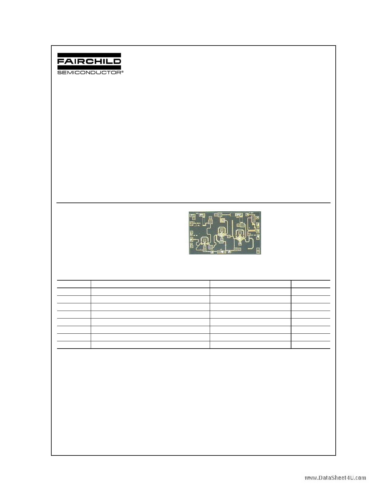
24 GHz Buffer Amplifier MMIC
General Description
The RMWB24001 is a 3-stage GaAs MMIC amplifier
designed as an 17 to 24 GHz Buffer Amplifier for use in
point to point and point to multi-point radios, and various
communications applications. In conjunction with other
amplifiers, multipliers and mixers it forms part of a complete
23 and 26 GHz transmit/receive chipset. The RMWB24001
utilizes our 0.25µm power PHEMT process and is
sufficiently versatile to serve in a variety of medium power
amplifier applications.
Features
• 4 mil Substrate
• Small-signal Gain 25dB (typ.)
• Saturated Power Out 17dBm (typ.)
• Voltage Detector Included to Monitor Pout
• Chip size 2.5mm x 1.5mm x 100µm
Device
Absolute Ratings
Symbol
Vd
Vg
Vdg
ID
PIN
TC
TSTG
RJC
Parameter
Positive DC Voltage (+4V Typical)
Negative DC Voltage
Simultaneous (Vd–Vg)
Positive DC Current
RF Input Power (from 50Ω source)
Operating Baseplate Temperature
Storage Temperature Range
Thermal Resistance (Channel to Backside)
Ratings
+6
-2
8
110
+11
-30 to +85
-55 to +125
148
Units
V
V
V
mA
dBm
°C
°C
°C/W
©2004 Fairchild Semiconductor Corporation
RMWB24001 Rev. D
1 page 
www.DataRSeheceot4Um.cmomended Procedure for Biasing and Operation
CAUTION: LOSS OF GATE VOLTAGE (Vg) WHILE
DRAIN VOLTAGE (Vd) IS PRESENT MAY DAMAGE THE
AMPLIFIER CHIP.
The following sequence of steps must be followed to
properly test the amplifier:
Step 1: Turn off RF input power.
Step 2: Connect the DC supply grounds to the ground of
the chip carrier. Slowly apply negative gate bias supply
voltage of -1.5V to Vg.
Step 3: Slowly apply positive drain bias supply voltage of
+4V to Vd.
Step 4: Adjust gate bias voltage to set the quiescent
current of Idq = 70mA.
Step 5: After the bias condition is established, the RF input
signal may now be applied at the appropriate frequency
band.
Step 6: Follow turn-off sequence of:
(i) Turn off RF input power,
(ii) Turn down and off drain voltage (Vd),
(iii) Turn down and off gate bias voltage (Vg).
Typical Characteristics
RMWB24001 24 GHz BA, Pout vs Pin Performance
On-Wafer Measurements, Vd = 4 V, Idq = 70 mA
20
18
16
14
12
24 GHz
10
21 GHz
8
17 GHz
6
4
2
0
-16 -14 -12 -10 -8 -6 -4 -2 0 2 4 6
Input Power (dBm)
8 10
©2004 Fairchild Semiconductor Corporation
RMWB24001 Rev. D
5 Page | ||
| Páginas | Total 7 Páginas | |
| PDF Descargar | [ Datasheet RMWB24001.PDF ] | |
Hoja de datos destacado
| Número de pieza | Descripción | Fabricantes |
| RMWB24001 | 24 GHZ Buffer Amp | Fairchild Semiconductor |
| Número de pieza | Descripción | Fabricantes |
| SLA6805M | High Voltage 3 phase Motor Driver IC. |
Sanken |
| SDC1742 | 12- and 14-Bit Hybrid Synchro / Resolver-to-Digital Converters. |
Analog Devices |
|
DataSheet.es es una pagina web que funciona como un repositorio de manuales o hoja de datos de muchos de los productos más populares, |
| DataSheet.es | 2020 | Privacy Policy | Contacto | Buscar |