|
|
|
PDF EL5172 Data sheet ( Hoja de datos )
| Número de pieza | EL5172 | |
| Descripción | (EL5172 / EL5372) 250MHz Differential Line Receivers | |
| Fabricantes | Intersil Corporation | |
| Logotipo | ||
Hay una vista previa y un enlace de descarga de EL5172 (archivo pdf) en la parte inferior de esta página. Total 16 Páginas | ||
|
No Preview Available !
®
Data Sheet
EL5172, EL5372
January 25, 2008
FN7311.8
250MHz Differential Line Receivers
The EL5172 and EL5372 are single and triple high
bandwidth amplifiers designed to extract the difference
signal from noisy environments. They are primarily targeted
for applications such as receiving signals from twisted-pair
lines or any application where common mode noise injection
is likely to occur.
The EL5172 and EL5372 are stable for a gain of one and
www.DataShereetq4uUir.ceosmtwo external resistors to set the voltage gain.
The output common mode level is set by the reference pin
(VREF), which has a -3dB bandwidth of over 120MHz.
Generally, this pin is grounded but it can be tied to any
voltage reference.
The output can deliver a maximum of ±60mA and is short
circuit protected to withstand a temporary overload
condition.
The EL5172 is available in the 8 Ld SOIC and 8 Ld MSOP
packages and the EL5372 in a 24 Ld QSOP package. Both
are specified for operation over the full -40°C to +85°C
temperature range.
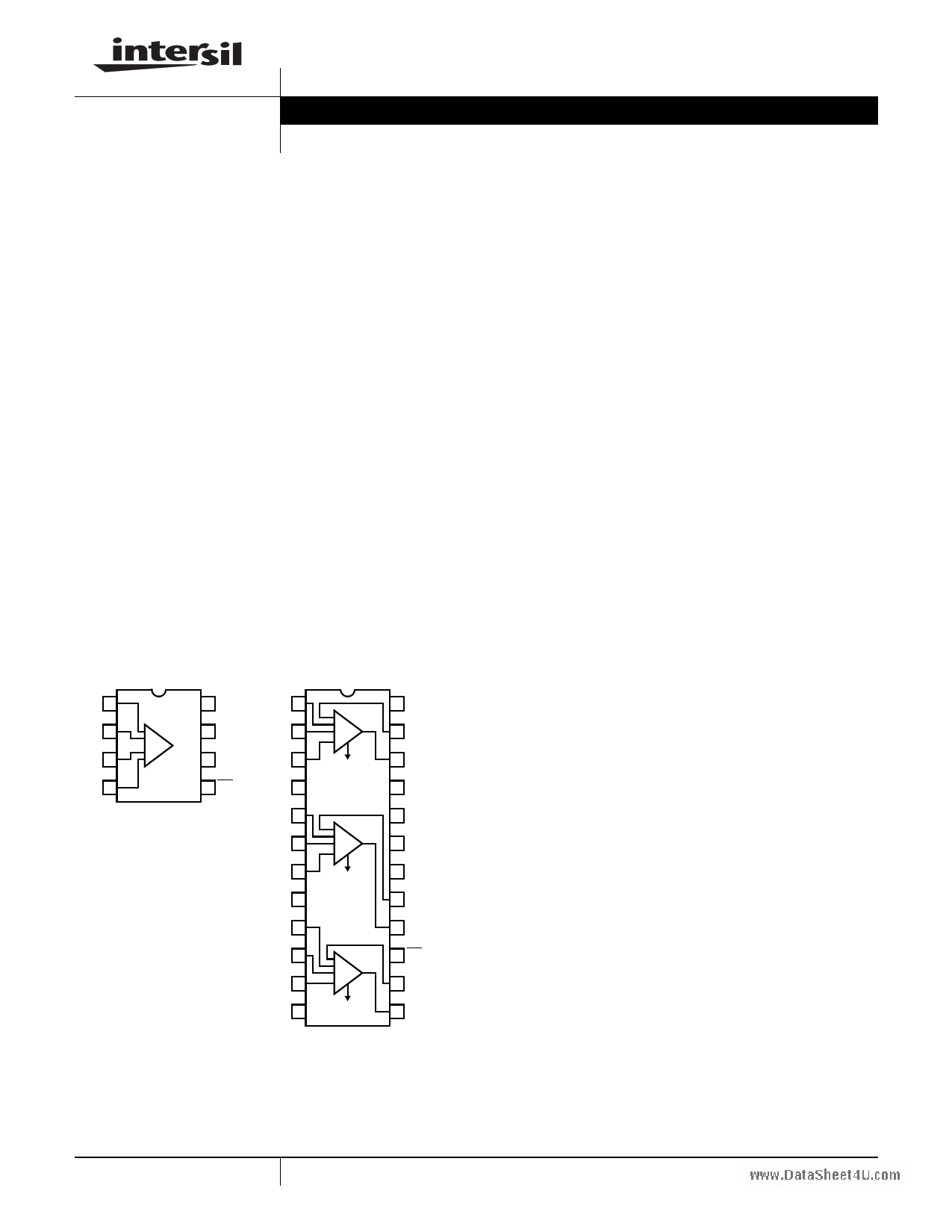
Pinouts
EL5172
(8 LD SOIC, MSOP)
TOP VIEW
EL5372
(24 LD QSOP)
TOP VIEW
FB 1
IN+ 2
IN- 3
REF 4
+
-
8 OUT REF1 1
7 VS-
INP1 2
6 VS+ INN1 3
5 EN
NC 4
REF2 5
INP2 6
INN2 7
NC 8
REF3 9
INP3 10
INN3 11
NC 12
+
-
+
-
+
-
24 NC
23 FB1
22 OUT1
21 NC
20 VSP
19 VSN
18 NC
17 FB2
16 OUT2
15 EN
14 FB3
13 OUT3
Features
• Differential input range ±2.3V
• 250MHz 3dB bandwidth
• 800V/µs slew rate
• 60mA maximum output current
• Single 5V or dual ±5V supplies
• Low power - 5mA to 6mA per channel
• Pb-free available (RoHS compliant)
Applications
• Twisted-pair receivers
• Differential line receivers
• VGA over twisted-pair
• ADSL/HDSL receivers
• Differential to single-ended amplification
• Reception of analog signals in a noisy environment
1 CAUTION: These devices are sensitive to electrostatic discharge; follow proper IC Handling Procedures.
1-888-INTERSIL or 1-888-468-3774 | Intersil (and design) is a registered trademark of Intersil Americas Inc.
Copyright © Intersil Americas Inc. 2002-2005, 2008. All Rights Reserved.
All other trademarks mentioned are the property of their respective owners.
1 page 
Pin Descriptions
EL5172
1
2
3
4
EL5372
5
6
7
8
www.DataSheet4U.com
1, 5, 9
2, 6, 10
3, 7, 11
4, 8, 12, 18, 21, 24
13, 16, 22
14, 17, 23
15
19
20
EL5172, EL5372
PIN NAME
FB
IN+
IN-
REF
EN
VS+
VS-
OUT
REF1, 2, 3
INP1, 2, 3
INN1, 2, 3
NC
OUT1, 2, 3
FB1, 2, 3
EN
VSN
VSP
PIN FUNCTION
Feedback input
Non-inverting input
Inverting input
Sets the common mode output voltage level
Enabled when this pin is floating or the applied voltage ≤ VS+ - 1.5
Positive supply voltage
Negative supply voltage
Output voltage
Reference input, controls common-mode output voltage
Non-inverting inputs
Inverting inputs
No connect; grounded for best crosstalk performance
Non-inverting outputs
Feedback from outputs
Enabled when this pin is floating or the applied voltage ≤ VS+ - 1.5
Negative supply
Positive supply
5 FN7311.8
January 25, 2008
5 Page 
EL5172, EL5372
Description of Operation and Application
Information
Product Description
The EL5172 and EL5372 are wide bandwidth, low power
and single/differential ended to single ended output
amplifiers. The EL5172 is a single channel differential to
single ended amplifier. The EL5372 is a triple channel
differential to single ended amplifier. The EL5172 and
EL5372 are internally compensated for closed loop gain of
+1 or greater. Connected in gain of 1 and driving a 500Ω
load, the EL5172 and EL5372 have a -3dB bandwidth of
250MHz. Driving a 150Ω load at gain of 2, the bandwidth is
about 50MHz. The bandwidth at the REF input is about
www.DataShe4e5t40UM.Hcozm. The EL5172 and EL5372 are available with a
power-down feature to reduce the power while the amplifier
is disabled.
Input, Output and Supply Voltage Range
The EL5172 and EL5372 have been designed to operate
with a single supply voltage of 5V to 10V or a split supplies
with its total voltage from 5V to 10V. The amplifiers have an
input common mode voltage range from -4.3V to 3.3V for
±5V supply. The differential mode input range (DMIR)
between the two inputs is about from -2.3V to +2.3V. The
input voltage range at the REF pin is from -3.6V to 3.3V. If
the input common mode or differential mode signal is outside
the above-specified ranges, it will cause the output signal to
be distorted.
The output of the EL5172 and EL5372 can swing from -3.8V
to 3.6V at 500Ω load at ±5V supply. As the load resistance
becomes lower, the output swing is reduced respectively.
Over All Gain Settings
The gain setting for the EL5172 and the EL5372 is similar to
the conventional operational amplifier. The output voltage is
equal to the difference of the inputs plus VREF and then
times the gain.
VO
=
(V
IN
+
–
VIN
-
+
VR
E
F
)
×
⎛
⎜
⎝
1
+
R-R----G-F--⎠⎟⎞
VIN+
VIN-
VREF
FB
RG
EN
+
-
Σ G/B
+
-
RF
VO
FIGURE 23.
Choice of Feedback Resistor and Gain Bandwidth
Product
For applications that require a gain of +1, no feedback
resistor is required. Just short the OUT pin to the FB pin. For
gains greater than +1, the feedback resistor forms a pole
with the parasitic capacitance at the inverting input. As this
pole becomes smaller, the amplifier's phase margin is
reduced. This causes ringing in the time domain and
peaking in the frequency domain. Therefore, RF has some
maximum value that should not be exceeded for optimum
performance. If a large value of RF must be used, a small
capacitor in the few Pico farad range in parallel with RF can
help to reduce the ringing and peaking at the expense of
reducing the bandwidth.
The bandwidth of the EL5172 and EL5372 depends on the
load and the feedback network. RF and RG appear in
parallel with the load for gains other than +1. As this
combination gets smaller, the bandwidth falls off.
Consequently, RF also has a minimum value that should not
be exceeded for optimum bandwidth performance. For a
gain of +1, RF = 0 is optimum. For the gains other than +1,
optimum response is obtained with RF between 500Ω to
1kΩ. For AV = 2 and RF = RG = 1kΩ, the BW is about 80MHz
and the frequency response is very flat.
The EL5172 and EL5372 have a gain bandwidth product of
100MHz. For gains ≥5, its bandwidth can be predicted by
Equation 1:
Gain × BW = 100MHz
(EQ. 1)
Driving Capacitive Loads and Cables
The EL5172 and EL5372 can drive 56pF capacitance in
parallel with 500Ω load to ground with 4dB of peaking at gain
of +1. If less peaking is desired in applications, a small
series resistor (usually between 5Ω to 50Ω) can be placed in
series with each output to eliminate most peaking. However,
this will reduce the gain slightly. If the gain setting is greater
than 1, the gain resistor RG can then be chosen to make up
for any gain loss which may be created by the additional
series resistor at the output.
When used as a cable driver, double termination is always
recommended for reflection-free performance. For those
applications, a back-termination series resistor at the
amplifier's output will isolate the amplifier from the cable and
allow extensive capacitive drive. However, other applications
may have high capacitive loads without a back-termination
resistor. Again, a small series resistor at the output can help
to reduce peaking.
Disable/Power-Down
The EL5172 and EL5372 can be disabled and its outputs
placed in a high impedance state. The turn-off time is about
1.4µs and the turn-on time is about 150ns. When disabled,
the amplifier's supply current is reduced to 80µA for IS+ and
11 FN7311.8
January 25, 2008
11 Page | ||
| Páginas | Total 16 Páginas | |
| PDF Descargar | [ Datasheet EL5172.PDF ] | |
Hoja de datos destacado
| Número de pieza | Descripción | Fabricantes |
| EL5170 | (EL5170 / EL5370) 100MHz Differential Twisted-Pair Drivers | Intersil Corporation |
| EL5171 | 250MHz Differential Twisted-Pair Drivers | Intersil Corporation |
| EL5172 | (EL5172 / EL5372) 250MHz Differential Line Receivers | Intersil Corporation |
| EL5173 | 450MHz Differential Twisted-Pair Drivers | Intersil Corporation |
| Número de pieza | Descripción | Fabricantes |
| SLA6805M | High Voltage 3 phase Motor Driver IC. |
Sanken |
| SDC1742 | 12- and 14-Bit Hybrid Synchro / Resolver-to-Digital Converters. |
Analog Devices |
|
DataSheet.es es una pagina web que funciona como un repositorio de manuales o hoja de datos de muchos de los productos más populares, |
| DataSheet.es | 2020 | Privacy Policy | Contacto | Buscar |