|
|
|
PDF AG606 Data sheet ( Hoja de datos )
| Número de pieza | AG606 | |
| Descripción | Push-Pull CATV Amplifier | |
| Fabricantes | WJ Communication | |
| Logotipo | ||
Hay una vista previa y un enlace de descarga de AG606 (archivo pdf) en la parte inferior de esta página. Total 5 Páginas | ||
|
No Preview Available !
AG606www.DataSheet4U.com
Push-Pull CATV Amplifier
The Communications Edge TM
Product Information
Product Features
x 50 – 860 MHz
x ±0.7 dB Gain Flatness
x +20 dBm P1dB
x +37 dBm Output IP3
x +73 dBm Output IP2
x -68 dBc CTB
+34 dBmV/channel, 79 channels
x -80 dBc CSO
+34 dBmV/channel, 79 channels
x Matched amplifiers for a
push-pull configuration
x +7V Single Positive Supply
x MTTF > 1000 Years
Applications
x CATV Head End Equipment
x CATV Line Amplifiers
x FTTH Repeaters
Product Description
The AG606 is a dual amplifier containing two internal
matched amplifiers optimal for a push-pull configuration.
The internal amplifiers employ InGaP HBT technology
for a cost-effective low-distortion solution.
The AG606 is ideal for drop amplifiers, splitters, and
other low to moderate power outside plant CATV
applications. The amplifier can also be useful in low
power headend applications such as linear laser drivers.
The AG606 has excellent VSWR when used in a 75 :
push-pull configuration. It is provided in a low-cost
environmentally-friendly lead-free/green/RoHS-compliant
SOIC-8 package.
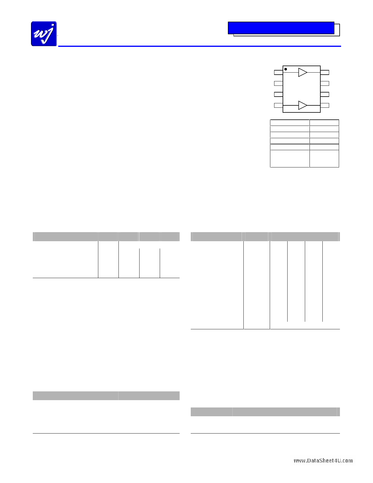
Functional Diagram
18
27
36
45
Function
Amp 1 Input
Amp 2 Input
Amp 2 Output
Amp 1 Output
Ground
Pin No.
1
4
5
8
2, 3, 6, 7,
Backside
paddle
Single-ended Device Specifications(1)
Parameter
Test Frequency
Gain
Output IP3 (2)
Device Current
Device Voltage
Units
MHz
dB
dBm
mA
V
Min
13.2
+33.5
76
Typ
800
14.3
+36
82.5
5.25
Max
15.5
90
1. Test conditions unless otherwise noted: T = 25 ºC, 800 MHz on each individual single-branch
amplifier in a 50¡ test fixture using a +7V supply and a 20.5 ¡ dropping resistor.
2. 3OIP measured with two tones at an output power of +5 dBm/tone separated by 1 MHz. The
suppression on the largest IM3 product is used to calculate the 3OIP using a 2:1 rule.
3. Typical parameters reflect performance in a push-pull application circuit.
4. Balun, board, and connector losses have not been extracted, but typically account of 0.4 dB loss
midband and 1.1 dB loss at 860 MHz.
5. Measured at +34 dBmV/channel, 79 channels Flat Loading.
6. OIP2 is measured at f1 + f2 at +5 dBm / tone.
Typical Performance (3)
Parameter
Frequency
Gain (4)
Input Return Loss
Output Return Loss
CTB (5)
CSO (5)
XMOD (5)
Output P1dB
Output IP2 (6)
Output IP3 (2)
Noise Figure (4)
Device Bias
Units
MHz
dB
dB
dB
dBc
dBc
dBc
dBm
dBm
dBm
dB
V
Typical
50 250 450 860
14.3 14.2 13.9 12.9
21 28 18 11
17 18 16 18
-69 -67 -67
-81 -87 -80
-60 -61 -60
+20.7 +20.5 +20.3 +22
+73.6 +76.1 +76.4 +76.6
+37.5 +37.5 +37.3 +39.2
5 5 5.3 5.9
+5.25 V @ 165 mA
Absolute Maximum Rating
Parameter
Operating Case Temperature
Storage Temperature
Supply Voltage
RF Input Power (continuous)
Junction Temperature
Rating
-40 to +85 qC
-55 to +125 qC
+7 V
+13dBm
+250 qC
Operation of this device above any of these parameters may cause permanent damage.
Ordering Information
Part No.
AG606-G
AG606-PCB
Description
Push-pull CATV Amplifier
(lead-free/green/RoHS-compliant SOIC8 Pkg)
Fully Assembled CATV Evaluation Board
Specifications and information are subject to change without notice.
WJ Communications, Inc Phone 1-800-WJ1-4401 FAX: 408-577-6621 e-mail: [email protected] Web site: www.wj.com
Page 1 of 5 April 2006
1 page 
AG606www.DataSheet4U.com
Push-Pull CATV Amplifier
The Communications Edge TM
Product Information
AG606-G (Lead-Free Package) Mechanical Information
This package is lead-free/green/RoHS-compliant. The plating material on the leads is NiPdAu. It is compatible with both lead-free
(maximum 260 qC reflow temperature) and lead (maximum 245 qC reflow temperature) soldering processes.
Outline Drawing
Product Marking
The component will be marked with an
“AG606G” designator with an alphanumeric
lot code on the top surface of the package.
The obsolete tin-lead package is marked with
an “AG606” designator followed by an
alphanumeric lot code.
Tape and reel specifications for this part are
located on the website in the “Application
Notes” section.
Land Pattern
Thermal Specifications
Parameter
Operating Case Temperature
Thermal Resistance, Rth (1)
Junction Temperature, Tj (2)
Rating
-40 to +85 qC
63 qC/W
142 qC
Notes:
1. The thermal resistance is referenced from the hottest part
of the junction to ground tab underneath the device.
2. This corresponds to the typical biasing condition of
+5.16V, 175 mA at an 85 ¥ C case temperature. A
minimum MTTF of 1 million hours is achieved for
junction temperatures below 177 ¥ C.
10000
1000
100
10
1
50
MTTF vs. GND Tab Temperature
ESD / MSL Information
ESD Rating:
Value:
Test:
Standard:
Class 1C
1000 to 2000 V
Human Body Model (HBM)
JEDEC Standard JESD22-A114
ESD Rating:
Value
Test:
Standard:
Class IV
Passes greater than 1000 V
Charge Device Model (CDM)
JEDEC Standard JESD22-C101
MSL Rating: Level 2 at +260 ¥ C convection reflow
Standard: JEDEC Standard J-STD-020A
Mounting Config. Notes
1. Ground / thermal vias are critical for the proper performance
of this device. Vias should use a .35mm (#80/.0135” )
diameter drill and have a final plated through diameter of
.25mm (.010” )
2. Add as much copper as possible to inner and outer layers
near the part to ensure optimal thermal performance.
3. To ensure reliable operation, device ground paddle-to-
ground pad solder joint is critical.
4. Add mounting screws near the part to fasten the board to a
heatsink. Ensure that the ground / thermal via region
contacts the heatsink.
5. For optimal thermal performance, expose soldermask on
backside where it contacts the heatsink.
6. RF trace width depends upon the PC board material and
construction.
7. Use 1 oz. Copper minimum.
8. If the PCB design rules allow, ground vias should be placed
under the land pattern for better RF and thermal
performance. Otherwise ground vias should be placed as
close to the land pattern as possible.
9. All dimensions are in mm. Angles are in degrees.
60 70 80 90
Tab Temperature (°C)
100
Specifications and information are subject to change without notice.
WJ Communications, Inc Phone 1-800-WJ1-4401 FAX: 408-577-6621 e-mail: [email protected] Web site: www.wj.com
¤
¤¤
¤
Page 5 of 5 April 2006
5 Page | ||
| Páginas | Total 5 Páginas | |
| PDF Descargar | [ Datasheet AG606.PDF ] | |
Hoja de datos destacado
| Número de pieza | Descripción | Fabricantes |
| AG602-86 | InGaP HBT Gain Block | ETC |
| AG602-86PCB | InGaP HBT Gain Block | ETC |
| AG602-89 | InGaP HBT Gain Block | ETC |
| AG602-89G | InGaP HBT Gain Block | ETC |
| Número de pieza | Descripción | Fabricantes |
| SLA6805M | High Voltage 3 phase Motor Driver IC. |
Sanken |
| SDC1742 | 12- and 14-Bit Hybrid Synchro / Resolver-to-Digital Converters. |
Analog Devices |
|
DataSheet.es es una pagina web que funciona como un repositorio de manuales o hoja de datos de muchos de los productos más populares, |
| DataSheet.es | 2020 | Privacy Policy | Contacto | Buscar |