|
|
|
PDF ADXRS150EB Data sheet ( Hoja de datos )
| Número de pieza | ADXRS150EB | |
| Descripción | Single Chip Rate Gyro Evaluation Board | |
| Fabricantes | Analog Devices | |
| Logotipo | ||
Hay una vista previa y un enlace de descarga de ADXRS150EB (archivo pdf) en la parte inferior de esta página. Total 1 Páginas | ||
|
No Preview Available !
؎150؇/s Single Chip Rate Gyro
Evaluation Board
ADXRS150EB
GENERAL DESCRIPTION
The ADXRS150EB is a simple evaluation board that allows the
user to quickly evaluate the performance of the ADXRS150ABG
yaw rate gyro. No additional external components are required
for operation. The ADXRS150EB has a 20-lead dual-in-line
(0.3 inch width by 0.1 inch pin spacing) interface that allows
the user to easily prototype products without having to deal with
BGA soldering. The 0.4 square inch outline of the ADXRS150EB
is still among the smallest gyros available today.
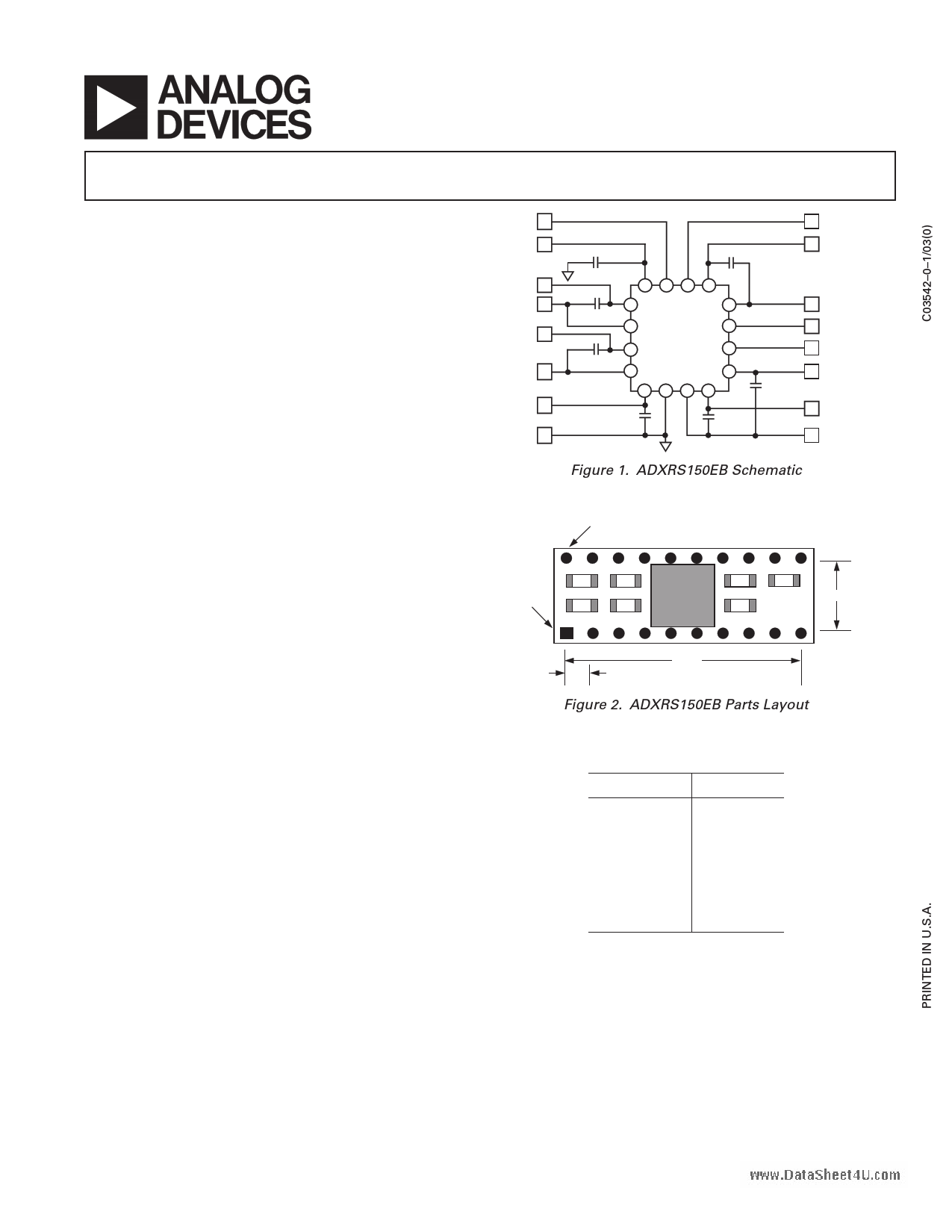
CIRCUIT DESCRIPTION
The schematic of the ADXRS150EB is shown in Figure 1.
It is identical to the suggested application shown in the
ADXRS150ABG data sheet.
The analog and power grounds (AGND and PGND) have
separate ground planes and are joined at one point. The user
may cut this trace if separate ground schemes are desired.
Note that the analog supply voltage and charge pump supply volt-
age (AVCC and PDD) are not connected on the ADXRS150EB
and that users must connect these as appropriate to their
application.
The parts layout of the ADXRS150EB is shown in Figure 2,
and the parts list for the ADXRS150EB is shown in Table I.
As delivered, the ADXRS150EB is set for 40 Hz bandwidth
(COUT = 22 nF). The user may add an external capacitor to
further reduce the bandwidth and improve the noise floor.
SPECIAL NOTES ON HANDLING
Note that the ADXRS150EB is not reverse polarity protected.
Reversing the power supply or applying inappropriate voltages
to any pin (outside the data sheet’s Absolute Maximum Ratings)
may damage the ADXRS150EB.
ST2 10
CP5 14
CP1 19
CP2 20
CP4 18
CP3 17
PDD 13
PGND 12
C3
C6
7D 4F 5F 1C
5A 1B
C2
4A
3F
ADXRS150ABG
7B 1E
C4
7C
3A
7E 6G 2G 1D
C7 C5
C1
11 ST1
3 SUMJ
2 RATEOUT
9 TEMP
7 2.5V
1 AVCC
4 CMID
8 AGND
Figure 1. ADXRS150EB Schematic
PIN 20
PIN 1
C2 C4
C1 C3
C6 C7
C5
0.3"
0.9"
0.1"
Figure 2. ADXRS150EB Parts Layout
Table I. ADXRS150EB Parts List
Component
C1
C2
C3
C4
C5
C6
C7
Value (nF)
100
22
22
22
100
47
100
REV. 0
Information furnished by Analog Devices is believed to be accurate and
reliable. However, no responsibility is assumed by Analog Devices for its
use, nor for any infringements of patents or other rights of third parties that
may result from its use. No license is granted by implication or otherwise
under any patent or patent rights of Analog Devices. Trademarks and
registered trademarks are the property of their respective companies.
One Technology Way, P.O. Box 9106, Norwood, MA 02062-9106, U.S.A.
Tel: 781/329-4700
www.analog.com
Fax: 781/326-8703 © 2003 Analog Devices, Inc. All rights reserved.
1 page | ||
| Páginas | Total 1 Páginas | |
| PDF Descargar | [ Datasheet ADXRS150EB.PDF ] | |
Hoja de datos destacado
| Número de pieza | Descripción | Fabricantes |
| ADXRS150EB | Single Chip Rate Gyro Evaluation Board | Analog Devices |
| Número de pieza | Descripción | Fabricantes |
| SLA6805M | High Voltage 3 phase Motor Driver IC. |
Sanken |
| SDC1742 | 12- and 14-Bit Hybrid Synchro / Resolver-to-Digital Converters. |
Analog Devices |
|
DataSheet.es es una pagina web que funciona como un repositorio de manuales o hoja de datos de muchos de los productos más populares, |
| DataSheet.es | 2020 | Privacy Policy | Contacto | Buscar |