|
|
|
PDF EL9111 Data sheet ( Hoja de datos )
| Número de pieza | EL9111 | |
| Descripción | (EL9111 / EL9112) Triple Differential Receiver/Equalizer | |
| Fabricantes | Intersil Corporation | |
| Logotipo | ||
Hay una vista previa y un enlace de descarga de EL9111 (archivo pdf) en la parte inferior de esta página. Total 12 Páginas | ||
|
No Preview Available !
®
Data Sheet
EL9111, EL9112
May 17, 2005
FN7450.1
Triple Differential Receiver/Equalizer
The EL9111 and EL9112 are triple channel differential
receivers and equalizers. They contains three high speed
differential receivers with five programmable poles. The
outputs of these pole blocks are then summed into an output
buffer. The equalization length is set with the voltage on a
single pin. The EL9111 and EL9112 also contain a 3-statable
output, enabling multiple devices to be connected in parallel
and used in a multiplexing application.
The gain can be adjusted up or down on each channel by
6dB using its VGAIN control signal. In addition, a further 6dB
of gain can be switched in to provide a matched drive into a
cable.
The EL9111 and EL9112 have a bandwidth of 150MHz and
consume just 108mA on ±5V supply. A single input voltage is
used to set the compensation levels for the required length
of cable.
The EL9111 is a special version of the EL9112 that decodes
syncs encoded onto the common modes of three pairs of
CAT-5 cable by the EL4543. (Refer to the EL4543 datasheet
for details.)
Thewww.DataSheet4U.com EL9111 and EL9112 are available in a 28-pin QFN
package and are specified for operation over the full -40°C to
+85°C temperature range.
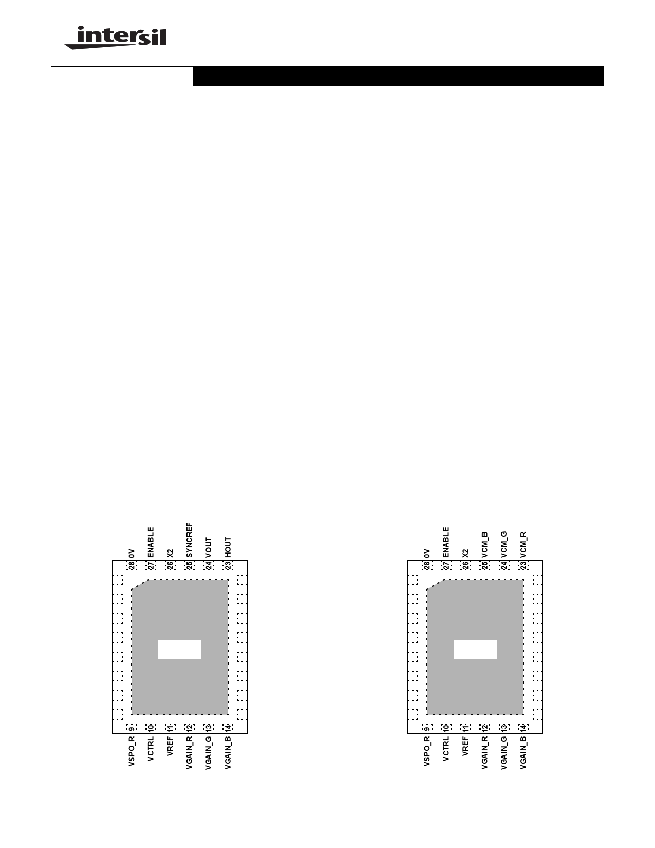
Pinouts
EL9111
(28-PIN QFN)
TOP VIEW
Features
• 150MHz -3dB bandwidth
• CAT-5 compensation
- 50MHz @ 1000 ft
- 125MHz @ 500 ft
• 108mA supply current
• Differential input range 3.2V
• Common mode input range -4V to +3.5V
• ±5V supply
• Output to within 1.5V of supplies
• Available in 28-pin QFN package
• Pb-free available (RoHS compliant)
Applications
• Twisted-pair receiving/equalizer
• KVM (Keyboard/Video/Mouse)
• VGA over twisted-pair
• Security video
EL9112
(28-PIN QFN)
TOP VIEW
VSMO_B 1
VOUT_B 2
VSPO_B 3
VSPO_G 4
VOUT_G 5
VSMO_G 6
VSMO_R 7
VOUT_R 8
THERMAL
PAD
22 VSP
21 VINM_B
20 VINP_B
19 VINM_G
18 VINP_G
17 VINM_R
16 VINP_R
15 VSM
VSMO_B 1
VOUT_B 2
VSPO_B 3
VSPO_G 4
VOUT_G 5
VSMO_G 6
VSMO_R 7
VOUT_R 8
THERMAL
PAD
22 VSP
21 VINM_B
20 VINP_B
19 VINM_G
18 VINP_G
17 VINM_R
16 VINP_R
15 VSM
1
CAUTION: These devices are sensitive to electrostatic discharge; follow proper IC Handling Procedures.
1-888-INTERSIL or 1-888-352-6832 | Intersil (and design) is a registered trademark of Intersil Americas Inc.
Copyright Intersil Americas Inc. 2005. All Rights Reserved
All other trademarks mentioned are the property of their respective owners.
1 page 
EL9111, EL9112
Pin Descriptions (Continued)
PIN EL9111IL
NUMBER PIN NAME
EL9111IL
PIN FUNCTION
26 X2 Logic signal for x1/x2 output gain setting
27 ENABLE Chip enable logic signal
28 0V 0V reference for output voltage
Typical Performance Curves
EL9112IL
PIN NAME
X2
ENABLE
0V
EL9112IL
PIN FUNCTION
Logic signal for x1/x2 output gain setting
Chip enable logic signal
0V reference for output voltage
5
X2=LOW
VGAIN=0V
3 VCTRL=0V
RLOAD=150Ω
1
-1
-3
-5
1M
10M
100M 200M
FREQUENCY (Hz)
FIGURE 1. FREQUENCY RESPONSE OF ALL CHANNELS
FIGURE 2. GAIN vs FREQUENCY ALL CHANNELS
FIGURE 3. GAIN vs FREQUENCY FOR VARIOUS VCTRL
FIGURE 4. GAIN vs FREQUENCY FOR VARIOUS VCTRL &
VGAIN
5 FN7450.1
May 17, 2005
5 Page 
EL9111, EL9112
Decoding is based on the EL4543 encoding scheme, as
described in Figure 27 and Table 1. The scheme is a three-
level system, which has been designed such that the sum of
the common mode voltages results in a fixed average DC
level with no AC content. This eliminates the effect of EMI
radiation into the common mode signals along the twisted
pairs of the cable
The common mode voltages are initially extracted by the
EL9111 from the three input pairs. These are then passed to
an internal logic decoding block to provide Horizontal and
Vertical sync output signals (HOUT and VOUT).
BLUE CM
OUT (CH A)
GREEN CM
OUT (CH B)
RED CM
OUT (CH C)
VSYNC
HSYNC
TIME (0.5ms/DIV)
FIGURE 27. H & V SYNCS ENCODED
TABLE 1. H AND V SYNC DECODING
RED CM
Mid
GREEN CM BLUE CM
High
Low
HSYNC
Low
High
Low
Mid Low
Low High Mid High
Mid
Low
High
High
NOTE: Level ‘Mid’ is halfway between ‘High’ and ‘Low’
VSYNC
Low
High
Low
High
11 FN7450.1
May 17, 2005
11 Page | ||
| Páginas | Total 12 Páginas | |
| PDF Descargar | [ Datasheet EL9111.PDF ] | |
Hoja de datos destacado
| Número de pieza | Descripción | Fabricantes |
| EL9110 | Differential Receiver/Equalizer | Intersil Corporation |
| EL9111 | (EL9111 / EL9112) Triple Differential Receiver/Equalizer | Intersil Corporation |
| EL9112 | (EL9111 / EL9112) Triple Differential Receiver/Equalizer | Intersil Corporation |
| EL9115 | Triple Analog Video Delay Line | Intersil Corporation |
| Número de pieza | Descripción | Fabricantes |
| SLA6805M | High Voltage 3 phase Motor Driver IC. |
Sanken |
| SDC1742 | 12- and 14-Bit Hybrid Synchro / Resolver-to-Digital Converters. |
Analog Devices |
|
DataSheet.es es una pagina web que funciona como un repositorio de manuales o hoja de datos de muchos de los productos más populares, |
| DataSheet.es | 2020 | Privacy Policy | Contacto | Buscar |