|
|
|
PDF EM6620 Data sheet ( Hoja de datos )
| Número de pieza | EM6620 | |
| Descripción | Ultra-low power microcontroller | |
| Fabricantes | EM Microelectronic | |
| Logotipo | ||
Hay una vista previa y un enlace de descarga de EM6620 (archivo pdf) en la parte inferior de esta página. Total 30 Páginas | ||
|
No Preview Available !
R EM MICROELECTRONIC - MARIN SA
EM6620
Ultra Low Power Microcontroller with 4x8 LCD Driver
Features
• Low Power - 2.1 µA active mode, LCD On
- 0.5 µA standby mode, LCD Off
- 0.1 µA sleep mode
@ 1.5V, 32kHz, 25°C
• Low Voltage - 1.2 to 3.6 V
• SVLD - metal mask programmable (2.0V)
• ROM
- 1280 × 16 bits
• RAM
- 64 × 4 bits
• 2 clocks per instruction cycle
• 72 basic instructions
• Oscillation supervisor
• Timer watchdog (2 sec)
• Max. 8 inputs ; port A, port B
• max. 4 outputs ; port B
• LCD 8 segments, 3 or 4 times multiplexed
• Universal 10-bit counter, PWM, event counter
• Prescaler down to 1 Hz (crystal = 32 KHz)
• 1/1000 sec, 12 bit binary coded decimal counter
with hard or software start/stop function
• Frequency output 1Hz, 2048 Hz, 32 KHz, PWM
• 7 internal interrupt sources (BCD counter,
• 2×10-bit counter, 3× prescaler, SVLD)
• 5 external interrupt sources (port A, compare)
Description
The EM6620 is an advanced single chip CMOS 4-
bit microcontroller. It contains ROM, RAM, power
on reset, watchdog timer, oscillation detection
circuit, 10 bit up/down counter, Millisecond counter,
prescaler, voltage level detector (SVLD), compare
input, frequency output, LCD driver and several
clock functions. The low voltage feature and low
power consumption make it the most suitable
controller for battery, stand alone and mobile
equipment. The EM6620 is manufactured using EM
Microeletronic’s Advanced Low Power (ALP)
CMOS Process.
Typical Applications
• Timing device
• Medical applications
• Domestic appliance
• Timer / sports timing devices
• Safety and security devices
• Automotive controls with display
• Measurement equipment
• Interactive system with display
• Bicycle computers
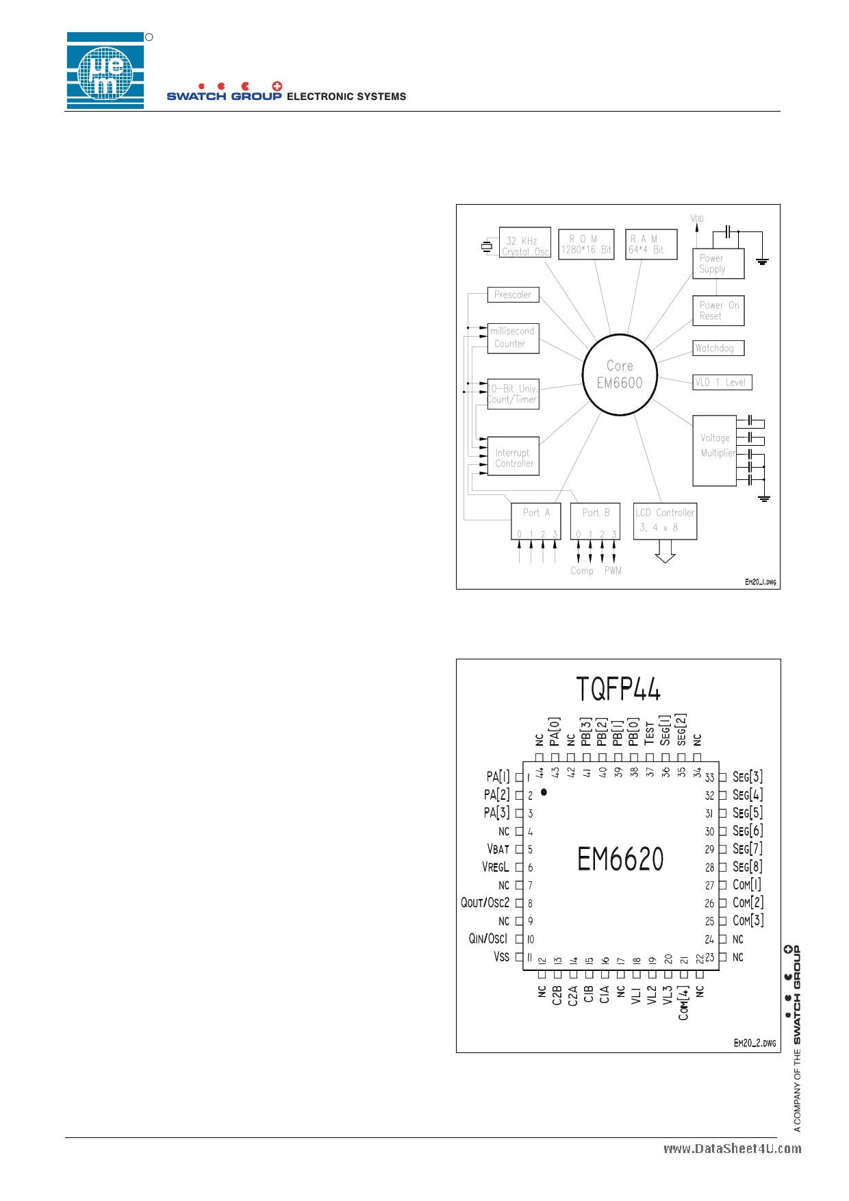
Figure 1. Architecture
Figure 2. Pin Configuration
Copyright © 2005, EM Microelectronic-Marin SA
1
www.emmicroelectronic.com
1 page 
R
EM6620
Figure 3. Typical configuration
LC D D isplay
crystal
all Capacitors 100nF
C1
VL1
C O M [4:1 ]
SEG [8:1]
C1 VL2
C1
VL3
QIN QOUT
C1A
C2 C1B
C2 C2A
C2B
Port A
Port B
EM6620
VDD (VBAT)
Vreg
Test
VSS
C3 C4
Copyright © 2005, EM Microelectronic-Marin SA
5
www.emmicroelectronic.com
5 Page 
R
EM6620
5. Oscillator and Prescaler
5.1 Oscillator
A built-in crystal oscillator generates the system operating clock for the CPU and peripheral blocks, from an
externally connected crystal (typically 32.768kHz). The oscillator circuit is supplied by the regulated voltage,
Vreg. In sleep mode the oscillator is stopped.
EM’s special design techniques guarantee the low current consumption of this oscillator. The external
impedance between the oscillator pads must be greater than 10 MOhm. Connection of any other components
to the two oscillator pads must be confirmed by EM Microelectronic-Marin SA.
5.2 Prescaler
The prescaler consists of fifteen elements divider chain which delivers clock signals for the peripheral circuits
such as timer/counter, buzzer, LCD voltage multiplier, debouncer and edge detectors, as well as generating
prescaler interrupts. The input to the prescaler is the system clock signal. Power on initializes the prescaler to
Hex(0001).
Table 5.2.1 Prescaler Clock Name Definition
Function
Name
32 KHz Xtal
System clock
Ck[16]
32768 Hz
System clock / 2
Ck[15]
16384 Hz
System clock / 4
Ck[14]
8192 Hz
System clock / 8
Ck[13]
4096 Hz
System clock/ 16
Ck[12]
2048 Hz
System clock / 32
Ck[11]
1024 Hz
System clock / 64
Ck[10]
512 Hz
System clock / 128
ck [9]
256 Hz
Function
System clock / 256
System clock / 512
System clock / 1024
System clock / 2048
System clock / 4096
System clock / 8192
System clock / 16384
System clock / 32768
Name
Ck[8]
Ck[7]
Ck[6]
Ck[5]
Ck[4]
Ck[3]
Ck[2]
Ck[1]
32 KHz Xtal
128 Hz
64 Hz
32 Hz
16 Hz
8 Hz
4 Hz
2 Hz
1 Hz
Table 5.2.2 Control of Prescaler Register RegPresc
Bit Name
Reset R/W Description
3 PWMOn 0
R/W see 10 bit counter
2 ResPresc 0
R/W Write Reset prescaler
1 -> Resets the divider chain
from Ck[14] down to
Ck[2], sets Ck[1].
0 -> No action.
1 PrIntSel 0
0 DebSel 0
The Read value is always '0'
R/W Interrupt select.
0 -> Interrupt from Ck[4]
1 -> Interrupt from Ck[6]
R/W Debouncer clock select.
0 -> Debouncer with Ck[8]
1 -> Debouncer with Ck[11] or
Ck[14]
Figure 8. Prescaler Frequency Timing
Prescaler Reset
System Clock
Ck[16]
Ck[15]
Ck[14]
Horizontal Scale Change
Ck[2]
Ck[1]
First positive edge of 1 Hz clock is 1s after
the falling reset edge
With DebSel = 1 one may choose either the Ck[11] or Ck[14] debouncer frequency by selecting the
corresponding metal mask option. Relative to 32kHz the corresponding max. debouncer times are then 2 ms or
0.25 ms. For the metal mask selection refer to chapter 16.1.5.
Switching the PrIntSel may generate an interrupt request. Avoid it with MaskIRQ32/8 = 0 selection during the
switching operation.
Copyright © 2005, EM Microelectronic-Marin SA
11
www.emmicroelectronic.com
11 Page | ||
| Páginas | Total 30 Páginas | |
| PDF Descargar | [ Datasheet EM6620.PDF ] | |
Hoja de datos destacado
| Número de pieza | Descripción | Fabricantes |
| EM6620 | Ultra-low power microcontroller | EM Microelectronic |
| EM6621 | Ultra-low power microcontroller | EM Microelectronic |
| EM6622 | Ultra-low power microcontroller | EM Microelectronic |
| EM6625 | Ultra-low power microcontroller | EM Microelectronic |
| Número de pieza | Descripción | Fabricantes |
| SLA6805M | High Voltage 3 phase Motor Driver IC. |
Sanken |
| SDC1742 | 12- and 14-Bit Hybrid Synchro / Resolver-to-Digital Converters. |
Analog Devices |
|
DataSheet.es es una pagina web que funciona como un repositorio de manuales o hoja de datos de muchos de los productos más populares, |
| DataSheet.es | 2020 | Privacy Policy | Contacto | Buscar |