|
|
|
PDF EK01 Data sheet ( Hoja de datos )
| Número de pieza | EK01 | |
| Descripción | EVALUATION KIT | |
| Fabricantes | Apex Microtechnology | |
| Logotipo | ||
Hay una vista previa y un enlace de descarga de EK01 (archivo pdf) en la parte inferior de esta página. Total 4 Páginas | ||
|
No Preview Available !
���������������
�������������������������������
����
��������������������������������������������������������������
INTRODUCTION
This easy-to-use kit provides a platform for the evaluation of
PWM amplifiers using the SA01 pin-out configuration. It can be
used to analyze a multitude of standard or proprietary circuit
configurations, and is flexible enough to do most standard
amplifier test configurations. The board is designed for surface
mounting all components except the switching amplifier.
The schematic is shown in Figure 2. Note that all of the
components shown on the schematic will probably not be used
for any single circuit. Some components will simply be omitted,
while others require installation of a jumper to complete the
signal path.
Only components unique to the EK01 are provided in this kit.
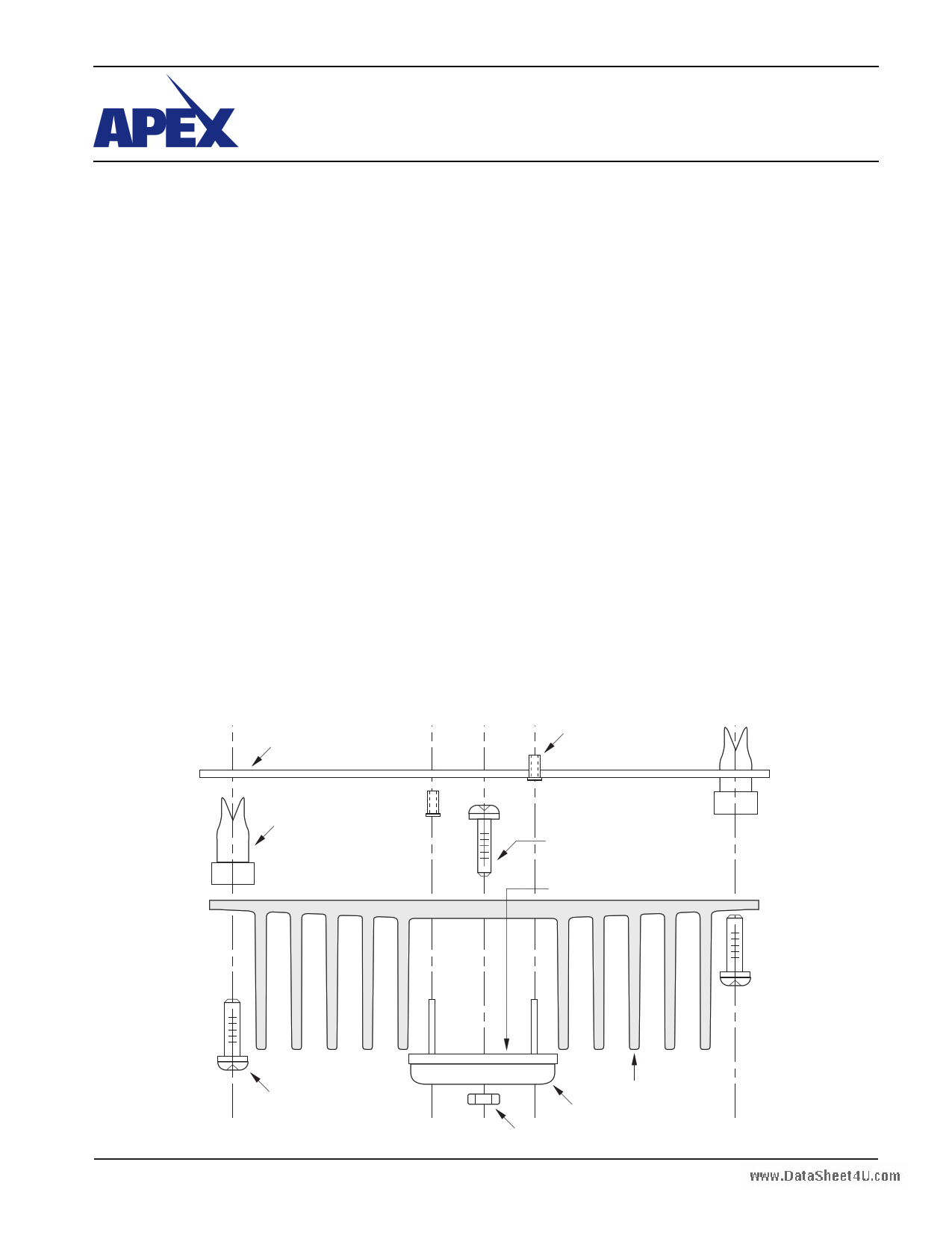
Hardware similar to that shown in figure 1 must be obtained lo-
cally. The PC board and the foot print of the heatsink measure
3" by 5".
PARTS LIST
Part #
HS16
MS04
EVAL07
60SPG00001
TW10
Description
Heatsink
PC mount Cage Jacks
PC Board
Spacer Grommets
Thermal Washer
Quantity
1
1 Bag/12 each
1
4
1 Box/10 each
ASSEMBLY
1. From the non-silk screen side, insert and solder cage jacks.
Be sure each one is fully seated.
2. From the non-silk screen side, push spacer grommets into
PC board until fully seated. Grommets will snug when screws
are inserted for heatsink mounting.
3. Apply TW10 thermal washer or a thin, even coat of thermal
grease to the bottom of the SA01. If grease is from a tube
make sure there is no sign separation of solids and liquids.
If from a jar, stir it prior to application.
4. Use #14 sleeving to insulate and align at least 2 opposite
pins of the amplifier.
5. Mount amplifier to heatsink using #6 screws and nuts. Do
not over torque.
6. Install components as needed. External connections may be
soldered directly or standard banana jacks may be soldered
to these pads.
7. Insert amplifier pins into cage jacks and fasten board to
heatsink.
BEFORE YOU GET STARTED
* All Apex amplifiers should be handled using proper ESD precautions.
* Always use the heatsink included in this kit with thermal grease.
* Torque the part to the specified 8 to 10 in-lbs (.9 to 1.13 N*M)
* Always use adequate power supply bypassing.
* Do not change connections while the circuit is powered.
* Initially set all power supplies to the minimum operating levels allowed in the device data sheet.
* Check for oscillations.
��������������������������
���������
������������������
��������������
��������������������
����������������������
��������������������������
FIGURE 1.
��������������������������������
��������
�������������������
���������������������
APEX MICROTECHNOLOGY CORPORATION • TELEPHONE (520) 690-8600 • FAX (520) 888-3329 • ORDERS (520) 690-8601 • EMAIL [email protected]1
1 page | ||
| Páginas | Total 4 Páginas | |
| PDF Descargar | [ Datasheet EK01.PDF ] | |
Hoja de datos destacado
| Número de pieza | Descripción | Fabricantes |
| EK01 | EVALUATION KIT | Apex Microtechnology |
| EK02 | Schottky Barrier Diodes 20V | Sanken electric |
| EK02666 | Schottky Barrier Diodes 20V | Sanken electric |
| EK03 | Schottky Barrier Diodes | Sanken electric |
| Número de pieza | Descripción | Fabricantes |
| SLA6805M | High Voltage 3 phase Motor Driver IC. |
Sanken |
| SDC1742 | 12- and 14-Bit Hybrid Synchro / Resolver-to-Digital Converters. |
Analog Devices |
|
DataSheet.es es una pagina web que funciona como un repositorio de manuales o hoja de datos de muchos de los productos más populares, |
| DataSheet.es | 2020 | Privacy Policy | Contacto | Buscar |