|
|
|
PDF CA3102 Data sheet ( Hoja de datos )
| Número de pieza | CA3102 | |
| Descripción | Dual High Frequency Differential Amplifier | |
| Fabricantes | Intersil Corporation | |
| Logotipo | ||
Hay una vista previa y un enlace de descarga de CA3102 (archivo pdf) en la parte inferior de esta página. Total 11 Páginas | ||
|
No Preview Available !
®
Data Sheet
October 12, 2005
CA3102
FN611.7
Dual High Frequency Differential Amplifier
For Low Power Applications Up to
500MHz
The CA3102 consists of two independent differential
amplifiers with associated constant current transistors on a
common monolithic substrate. The six transistors which
comprise the amplifiers are general purpose devices which
exhibit low 1/f noise and a value of fT in excess of 1GHz.
These features make the CA3102 useful from DC to
500MHz. Bias and load resistors have been omitted to
provide maximum application flexibility.
The monolithic construction of the CA3102 provides close
electrical and thermal matching of the amplifiers. This
feature makes this device particularly useful in dual channel
applications where matched performance of the two
channels is required.
The CA3102 has a separate substrate connection for greater
design flexibility.
Ordering Information
PART NUMBER TEMP.
(BRAND)
RANGE (oC)
PACKAGE
PKG.
DWG. #
CA3102E
(CA3102E)
-55 to 125 14 Ld PDIP
E14.3
CA3102M
(3102)
-55 to 125 14 Ld SOIC
M14.15
CA3102MZ
(CA3102MZ)
(Note)
-55 to 125 14 Ld SOIC
(Pb-free)
M14.15
NOTE: Intersil Pb-free plus anneal products employ special Pb-free
material sets; molding compounds/die attach materials and 100%
matte tin plate termination finish, which are RoHS compliant and
compatible with both SnPb and Pb-free soldering operations. Intersil
Pb-free products are MSL classified at Pb-free peak reflow
temperatures that meet or exceed the Pb-free requirements of
IPC/JEDEC J STD-020.
Features
• Power Gain 23dB (Typ) . . . . . . . . . . . . . . . . . . . . 200MHz
• Noise Figure 4.6dB (Typ) . . . . . . . . . . . . . . . . . . . 200MHz
• Two Differential Amplifiers on a Common Substrate
• Independently Accessible Inputs and Outputs
• Full Military Temperature Range . . . . . . . -55oC to 125oC
• Pb-Free Plus Anneal Available (RoHS Compliant)
Applications
• VHF Amplifiers
• VHF Mixers
• Multifunction Combinations - RF/Mixer/Oscillator;
Converter/IF
• IF Amplifiers (Differential and/or Cascode)
• Product Detectors
• Doubly Balanced Modulators and Demodulators
• Balanced Quadrature Detectors
• Cascade Limiters
• Synchronous Detectors
• Balanced Mixers
• Synthesizers
• Balanced (Push-Pull) Cascode Amplifiers
• Sense Amplifiers
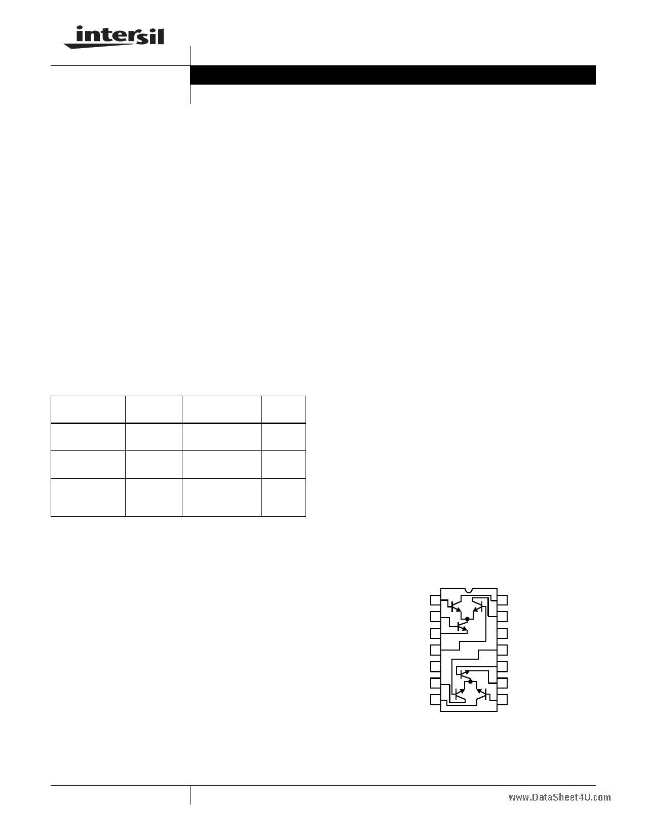
Pinout
CA3102
(PDIP, SOIC)
TOP VIEW
1
2
3
4
SUBSTRATE 5
6
7
14
13
12 SUBSTRATE
11
10
9
8
1
CAUTION: These devices are sensitive to electrostatic discharge; follow proper IC Handling Procedures.
1-888-INTERSIL or 1-888-468-3774 | Intersil (and design) is a registered trademark of Intersil Americas Inc.
Copyright Intersil Americas Inc. 2002, 2005. All Rights Reserved
All other trademarks mentioned are the property of their respective owners.
1 page 
Typical Performance Curves
0.5
TA = 25oC
0.4
0.3
CA3102
100
10
1.0
TA = -40oC
TA = 25oC
TA = 85oC
0.2
0.1
1
EMITTER CURRENT (mA)
10
FIGURE 4. INPUT OFFSET VOLTAGE vs EMITTER CURRENT
1.0 TA = 85oC
TA = 25oC
0.9 TA = -40oC
0.8
0.7
0.6
0.5
0.1
1.0
COLLECTOR CURRENT (mA)
10
FIGURE 6. BASE-TO-EMITTER VOLTAGE vs COLLECTOR
CURRENT
3
TA = 25oC
2
CCI
1
TERMINALS 14 AND 1; 7 AND 8
TERMINALS 13 AND 4; 6 AND 11
0
012 3
45
CCB
6 7 8 9 10 11 12 13 14
BIAS VOLTAGE (V)
FIGURE 8. CAPACITANCE vs DC BIAS VOLTAGE
5
0.1
0.1
1.0
EMITTER CURRENT (mA)
10
FIGURE 5. INPUT BIAS CURRENT vs EMITTER CURRENT
1000
100
10
VCB = 15V
VCB = 10V
VCB = 5V
1.0
0.1
0.01
-100 -75 -50 -25 0 25 50
TEMPERATURE (οC)
75 100
FIGURE 7. COLLECTOR CUTOFF CURRENT vs TEMPERATURE
70
60
TA = 25oC
V+ = 6V, V- = -6V
50 f = 1kHz
40
30
20
10
0
-10
-20
-30
-40
-50
0 -1 -2 -3
-4 -5
-6
BIAS VOLTAGE ON TERMINALS 2 AND 10 (V)
FIGURE 9. VOLTAGE GAIN vs DC BIAS VOLTAGE
-7
5 Page 
CA3102
Small Outline Plastic Packages (SOIC)
N
INDEX
AREA
E
-B-
H
0.25(0.010) M B M
123
-A-
D
SEATING PLANE
A
L
h x 45o
-C-
e A1
B
0.25(0.010) M C A M B S
µα
0.10(0.004)
C
NOTES:
1. Symbols are defined in the “MO Series Symbol List” in Section 2.2 of
Publication Number 95.
2. Dimensioning and tolerancing per ANSI Y14.5M-1982.
3. Dimension “D” does not include mold flash, protrusions or gate burrs.
Mold flash, protrusion and gate burrs shall not exceed 0.15mm (0.006
inch) per side.
4. Dimension “E” does not include interlead flash or protrusions. Interlead
flash and protrusions shall not exceed 0.25mm (0.010 inch) per side.
5. The chamfer on the body is optional. If it is not present, a visual index
feature must be located within the crosshatched area.
6. “L” is the length of terminal for soldering to a substrate.
7. “N” is the number of terminal positions.
8. Terminal numbers are shown for reference only.
9. The lead width “B”, as measured 0.36mm (0.014 inch) or greater
above the seating plane, shall not exceed a maximum value of
0.61mm (0.024 inch).
10. Controlling dimension: MILLIMETER. Converted inch dimensions
are not necessarily exact.
M14.15 (JEDEC MS-012-AB ISSUE C)
14 LEAD NARROW BODY SMALL OUTLINE PLASTIC
PACKAGE
INCHES
MILLIMETERS
SYMBOL MIN MAX MIN MAX NOTES
A
0.0532 0.0688 1.35
1.75
-
A1 0.0040 0.0098 0.10 0.25
-
B 0.013 0.020 0.33 0.51
9
C
0.0075 0.0098 0.19
0.25
-
D
0.3367 0.3444 8.55
8.75
3
E
0.1497 0.1574 3.80
4.00
4
e 0.050 BSC 1.27 BSC -
H
0.2284 0.2440 5.80
6.20
-
h
0.0099 0.0196 0.25
0.50
5
L 0.016 0.050 0.40 1.27
6
N 14
14 7
α 0o 8o 0o 8o -
Rev. 0 12/93
All Intersil U.S. products are manufactured, assembled and tested utilizing ISO9000 quality systems.
Intersil Corporation’s quality certifications can be viewed at www.intersil.com/design/quality
Intersil products are sold by description only. Intersil Corporation reserves the right to make changes in circuit design, software and/or specifications at any time without
notice. Accordingly, the reader is cautioned to verify that data sheets are current before placing orders. Information furnished by Intersil is believed to be accurate and
reliable. However, no responsibility is assumed by Intersil or its subsidiaries for its use; nor for any infringements of patents or other rights of third parties which may result
from its use. No license is granted by implication or otherwise under any patent or patent rights of Intersil or its subsidiaries.
For information regarding Intersil Corporation and its products, see www.intersil.com
11
11 Page | ||
| Páginas | Total 11 Páginas | |
| PDF Descargar | [ Datasheet CA3102.PDF ] | |
Hoja de datos destacado
| Número de pieza | Descripción | Fabricantes |
| CA3100 | Operational Amplifier | Harris Corporation |
| CA3102 | Dual High Frequency Differential Amplifier | Intersil Corporation |
| CA3102 | (CA30xx) Differential Amplifiers | RCA Solid State |
| CA3102 | (CA3049 / CA3102) Dual High Frequency Differential Amplifiers | Harris Semiconductor |
| Número de pieza | Descripción | Fabricantes |
| SLA6805M | High Voltage 3 phase Motor Driver IC. |
Sanken |
| SDC1742 | 12- and 14-Bit Hybrid Synchro / Resolver-to-Digital Converters. |
Analog Devices |
|
DataSheet.es es una pagina web que funciona como un repositorio de manuales o hoja de datos de muchos de los productos más populares, |
| DataSheet.es | 2020 | Privacy Policy | Contacto | Buscar |