|
|
|
PDF A16450 Data sheet ( Hoja de datos )
| Número de pieza | A16450 | |
| Descripción | Universal Asynchronous Receiver/Transmitter | |
| Fabricantes | Altera Corporation | |
| Logotipo | ||
Hay una vista previa y un enlace de descarga de A16450 (archivo pdf) en la parte inferior de esta página. Total 16 Páginas | ||
|
No Preview Available !
September 1996, ver. 1
®
a16450
Universal Asynchronous
Receiver/Transmitter
Data Sheet
Features
General
Description
s a16450 MegaCore function implementing a universal asynchronous
receiver/transmitter (UART)
s Optimized for FLEX® and MAX® architectures
s Programmable word length, stop bits, and parity
s Full duplex operation
s Programmable baud rate generator
s Prioritized interrupt control
s Internal diagnostic/loopback capabilities
s Uses approximately 372 FLEX logic elements (LEs)
s Functionally based on the National Semiconductor Corporation
NS16450 device, except as noted in “Variations & Clarifications” on
page 79
The a16450 MegaCore function implements a universal asynchronous
receiver/transmitter (UART), which provides an interface between a
microprocessor and a serial communications channel. The a16450
receives and transwwmw.DitastaSdheaett4aU.cionm a variety of configurations, including 5-, 6-,
7-, or 8-bit data words; odd, even, or no parity; and 1, 1.5, or 2 stop bits.
The a16450 includes an internal baud rate generator and interrupt
control. See Figure 1.
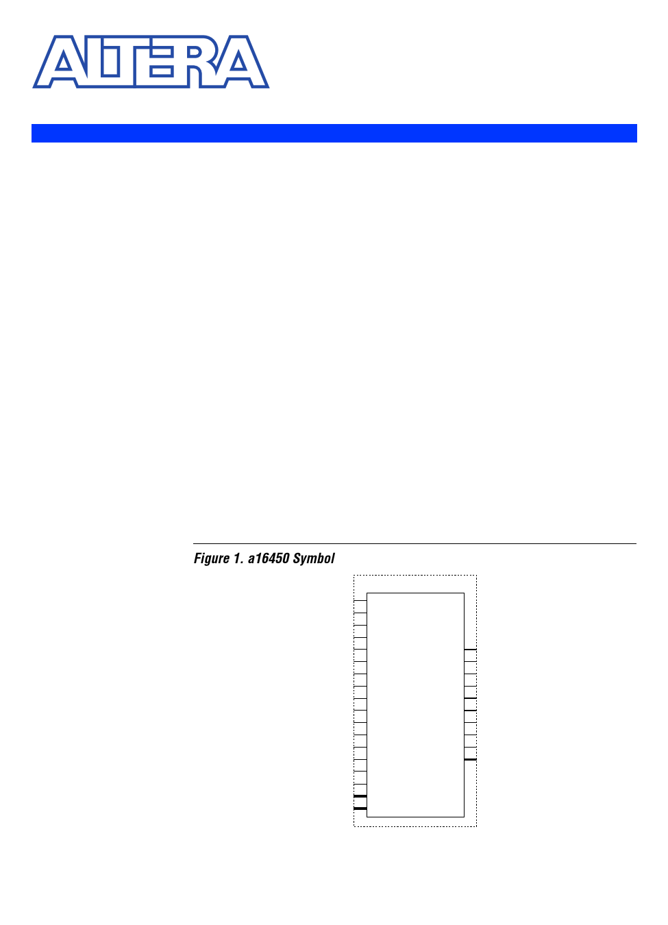
Figure 1. a16450 Symbol
A16450
nADS
CLK
CS0
CS1
nCS2
nCTS
nDCD
nDSR
MR
RCLK
RD
nRD
nRI
SIN
WR
nWR
nBAUDOUT
CSOUT
DDIS
nDTR
INTR
nOUT1
nOUT2
nRTS
SOUT
DOUT[7..0]
A[2..0]
DIN[7..0]
Altera Corporation
A-DS-A16450-01
65
1 page 
a16450 Universal Asynchronous Receiver/Transmitter Data Sheet
Register Address Map
The state of the a[2..0] inputs determines which internal register the
microprocessor addresses. See Table 2.
The divisor register access bit (drab) allows access to the divisor register.
The drab is bit 7 of the line control register.
Table 2. Register Address Map
drab (1) a2 a1 a0
Register
0 0 0 0 Receiver buffer register—read only
Transmitter holding register—write only
1 0 0 0 Divisor register (LSB)
0 0 0 1 Interrupt enable register
1 0 0 1 Divisor register (MSB)
X 0 1 0 Interrupt ID register
X 0 1 1 Line control register
X 1 0 0 Modem control register
X 1 0 1 Line status register
X 1 1 0 Modem status register
X 1 1 1 Scratchpad register
Note:
(1) The X indicates “don’t care.”
Registers
The a16450 MegaCore function contains the following registers:
s Receiver buffer
s Transmitter holding
s Divisor
s Interrupt enable
s Interrupt identification
s Line control
s Modem control
s Line status
s Modem status
s Scratchpad
Altera Corporation
69
5 Page 
a16450 Universal Asynchronous Receiver/Transmitter Data Sheet
Table 9. Line Status Register Format
Bit Signal
Description
0 rdr Receiver data ready. Indicates that an incoming word has been received and transferred to the
receiver buffer register. When bit 0 is set to a logic high, a receive data available interrupt is
generated. Bit 0 is cleared by reading the receiver buffer register.
1 oe Overrun error. Indicates that new data wrote over unread data in the receiver buffer register.
When bit 1 is set to a logic high, a receiver line status interrupt is generated. Bit 1 is cleared by
reading the line status register.
2 pe Parity error. Indicates that newly received data had incorrect parity. When bit 2 is set to a logic
high, a receiver line status interrupt is generated. Bit 2 is cleared by reading the line status
register.
3 fe Framing error. Indicates that newly received data had an invalid stop bit. When bit 3 is set to a
logic high, a receiver line status interrupt is generated. Bit 2 is cleared by reading the line status
register.
4 bi Break interrupt. Indicates that a break condition was detected on the serial input. A break
condition occurs when the serial data in (sin) is held at logic low for longer than one full word
transmission. When bit 4 is set to a logic high, a receiver line status interrupt is generated. Bit 4
is cleared by reading the line status register.
5 thre Transmitter holding register empty. Indicates that the a16450 is ready to accept a new data
word from the microprocessor for transmission. When bit 5 is set to a logic high, a transmitter
holding register empty interrupt is generated. Bit 5 is cleared by reading the interrupt ID register
or by writing to the transmitter holding register.
6 tre Transmitter empty. Indicates that the transmitter holding register and the transmitter shift
register are both empty.
7 – Not used. This read-only bit is always set to a logic low.
Modem Status Register
The modem status register enables the microprocessr to examine the
condition of the modem interface inputs. Table 10 shows the modem
status register format.
Altera Corporation
75
11 Page | ||
| Páginas | Total 16 Páginas | |
| PDF Descargar | [ Datasheet A16450.PDF ] | |
Hoja de datos destacado
| Número de pieza | Descripción | Fabricantes |
| A1645 | PNP Transistor - 2SA1645 | NEC |
| A16450 | Universal Asynchronous Receiver/Transmitter | Altera Corporation |
| Número de pieza | Descripción | Fabricantes |
| SLA6805M | High Voltage 3 phase Motor Driver IC. |
Sanken |
| SDC1742 | 12- and 14-Bit Hybrid Synchro / Resolver-to-Digital Converters. |
Analog Devices |
|
DataSheet.es es una pagina web que funciona como un repositorio de manuales o hoja de datos de muchos de los productos más populares, |
| DataSheet.es | 2020 | Privacy Policy | Contacto | Buscar |