|
|
|
PDF ADXL204 Data sheet ( Hoja de datos )
| Número de pieza | ADXL204 | |
| Descripción | Dual-Axis i MEMS Accelerometer | |
| Fabricantes | Analog Devices | |
| Logotipo | ||
Hay una vista previa y un enlace de descarga de ADXL204 (archivo pdf) en la parte inferior de esta página. Total 12 Páginas | ||
|
No Preview Available !
www.DataSheet4U.com
Precision ±1.7 g Single-/Dual-Axis
i MEMS® Accelerometer
ADXL204
FEATURES
High performance, dual-axis accelerometer on a
single IC chip
Specified at VS = 3.3 V
5 mm × 5 mm × 2 mm LCC package
Better than 2 mg resolution at 60 Hz
Low power: 500 μA at VS = 3.3 V (typical)
High zero g bias stability
High sensitivity accuracy
–40°C to +125°C temperature range
X-axis and Y-axis aligned to within 0.1° (typical)
BW adjustment with a single capacitor
Single-supply operation
3500 g shock survival
RoHS compliant
Compatible with Sn/Pb- and Pb-free solder processes
APPLICATIONS
Vehicle dynamic control (VDC)/electronic stability program
(ESP) systems
Electronic chassis controls
Electronic braking
Platform stabilization/leveling
Navigation
Alarms and motion detectors
High accuracy, 2-axis tilt sensing
GENERAL DESCRIPTION
The ADXL204 is a high precision, low power, complete dual-
axis accelerometer with signal-conditioned voltage outputs, all
on a single monolithic IC. Like the ADXL203, it measures
acceleration with a full-scale range of ±1.7 g; however, the
ADXL204 is tested and specified for 3.3 V supply voltage,
whereas the ADXL203 is tested and specified at 5 V. Both parts
function well over a wide 3 V to 6 V operating voltage range.
The ADXL204 can measure both dynamic acceleration (for
example, vibration) and static acceleration (for example, gravity).
The typical noise floor is 170 μg/√Hz, allowing signals below
2 mg (0.1° of inclination) to be resolved in tilt sensing
applications using narrow bandwidths (<60 Hz).
The user selects the bandwidth of the accelerometer using
Capacitor CX and Capacitor CY at the XOUT and YOUT pins.
Bandwidths of 0.5 Hz to 2.5 kHz can be selected to suit the
application.
The ADXL204 is available in a 5 mm × 5 mm × 2 mm,
8-terminal hermetic LCC package.
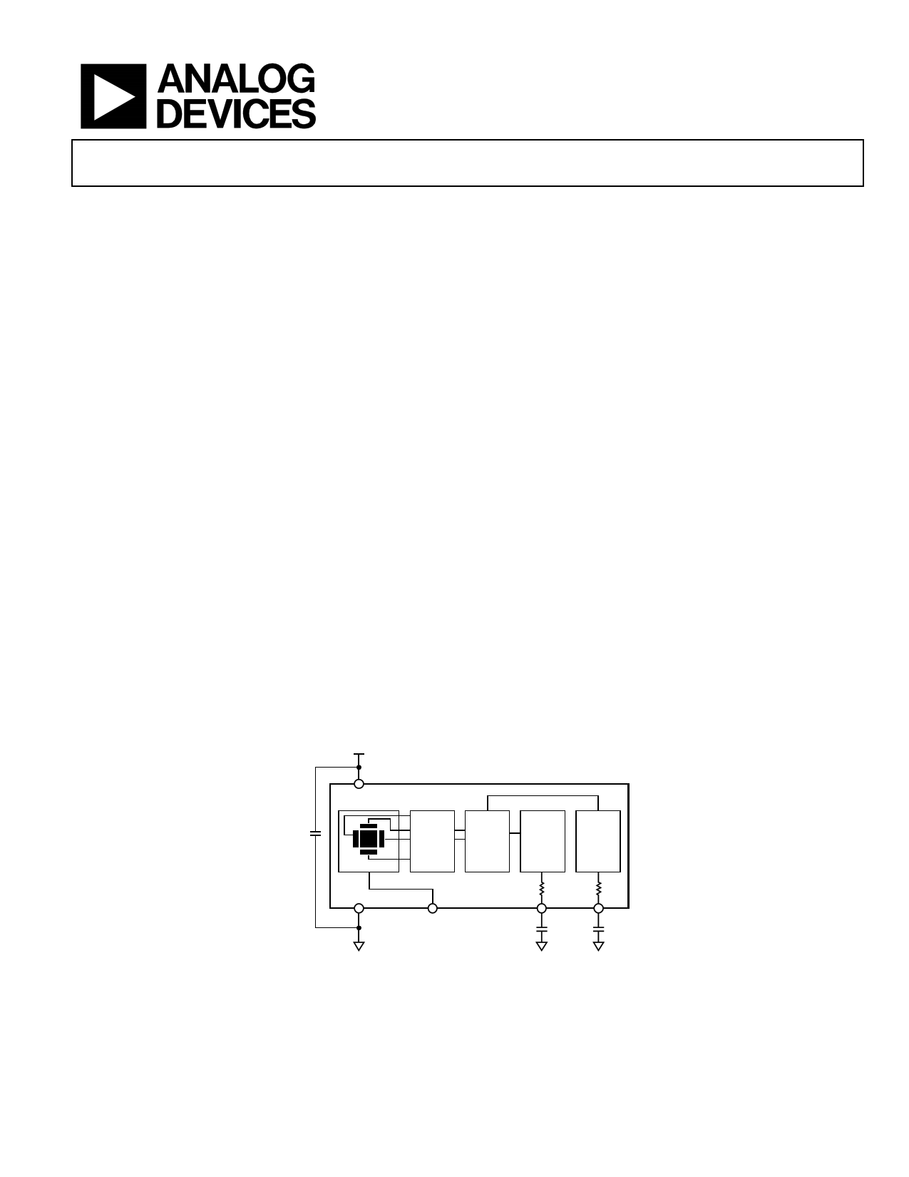
FUNCTIONAL BLOCK DIAGRAM
+5V
VS
ADXL204
CDC
SENSOR
COM
AC
AMP
DEMOD
OUTPUT
AMP
OUTPUT
AMP
RFILT
32kΩ
RFILT
32kΩ
ST
YOUT
XOUT
CY CX
Figure 1.
Rev. A
Information furnished by Analog Devices is believed to be accurate and reliable. However, no
responsibility is assumed by Analog Devices for its use, nor for any infringements of patents or other
rights of third parties that may result from its use. Specifications subject to change without notice. No
license is granted by implication or otherwise under any patent or patent rights of Analog Devices.
Trademarksandregisteredtrademarksarethepropertyoftheirrespectiveowners.
One Technology Way, P.O. Box 9106, Norwood, MA 02062-9106, U.S.A.
Tel: 781.329.4700
www.analog.com
Fax: 781.461.3113
©2006 Analog Devices, Inc. All rights reserved.
1 page 
PIN CONFIGURATION AND FUNCTION DESCRIPTIONS
ADXL204E
TOP VIEW
(Not to Scale)
ST 1
DNC 2
COM 3
VS
8
+Y
+X
4
DNC
7 XOUT
6 YOUT
5 DNC
Figure 3. Pin Configuration
Table 5. Pin Function Descriptions
Pin No.
Mnemonic
1 ST
2 DNC
3 COM
4 DNC
5 DNC
6 YOUT
7 XOUT
8 VS
Description
Self Test
Do Not Connect
Common
Do Not Connect
Do Not Connect
Y Channel Output
X Channel Output
3 V to 6 V
ADXL204
Rev. A | Page 5 of 12
5 Page 
Peak-to-peak noise values give the best estimate of the uncertainty
in a single measurement and is estimated by 6 × rms. Table 8
gives the typical noise output of the ADXL204 for various CX
and CY values.
Table 8. Filter Capacitor Selection (CX, CY)
CX, CY RMS Noise Peak-to-Peak Noise
Bandwidth(Hz) (μF) (mg)
Estimate (mg)
10
0.47 0.7
4.1
50
0.1 1.5
9.1
100
0.047 2.2
12.9
500
0.01 4.8
28.8
USING THE ADXL204 WITH OPERATING VOLTAGES
OTHER THAN 3.3 V
The ADXL204 is tested and specified at VS = 3.3 V; however, it
can be powered with VS as low as 3 V or as high as 6 V. Some
performance parameters change as the supply voltage is varied.
The ADXL204 output is ratiometric, so the output sensitivity, or
scale factor, varies proportionally to supply voltage. At VS = 3 V,
the output sensitivity is typically 560 mV/g. At VS = 5 V, the
output sensitivity is typically 1000 mV/g.
The zero g bias output is also ratiometric, so the zero g output is
nominally equal to VS/2 at all supply voltages.
The output noise is not ratiometric but is absolute in volts;
therefore, the noise density decreases as the supply voltage
increases. This is because the scale factor (mV/g) increases
while the noise voltage remains constant. At VS = 3 V, the noise
density is typically 190 μg/√Hz. At VS = 5 V, the noise density is
typically 110 μg/√Hz.
Self-test response in g is roughly proportional to the square of
the supply voltage. However, when ratiometricity of sensitivity
is factored in with supply voltage, self-test response in volts is
roughly proportional to the cube of the supply voltage. This
means at VS = 3 V, the self-test response is approximately
equivalent to 150 mV, or equivalent to 270 mg (typical). At
VS = 5 V, the self-test response is approximately equivalent to
750 mV, or equivalent to 750 mg (typical).
The supply current decreases as the supply voltage decreases.
Typical current consumption at VDD = 5 V is 750 μA.
ADXL204
USING THE ADXL204 AS A DUAL-AXIS TILT SENSOR
One of the most popular applications of the ADXL204 is tilt
measurement. An accelerometer uses the force of gravity as an
input vector to determine the orientation of an object in space.
An accelerometer is most sensitive to tilt when its sensitive
axis is perpendicular to the force of gravity, that is, parallel to
the earth’s surface. At this orientation, its sensitivity to changes
in tilt is highest. When the accelerometer is oriented on axis to
gravity, that is, near its +1 g or –1 g reading, the change in
output acceleration per degree of tilt is negligible. When the
accelerometer is perpendicular to gravity, its output changes
nearly 17.5 mg per degree of tilt. At 45°, its output changes
at only 12.2 mg per degree and resolution declines.
Dual-Axis Tilt Sensor: Converting Acceleration to Tilt
When the accelerometer is oriented, so both its x-axis and
y-axis are parallel to the earth’s surface, it can be used as a 2-axis
tilt sensor with a roll axis and a pitch axis. Once the output
signal from the accelerometer is converted to an acceleration
that varies between –1 g and +1 g, the output
tilt in degrees is calculated as:
PITCH = ASIN(AX/1 g)
ROLL = ASIN(AY/1 g)
Be sure to account for overranges. It is possible for the
accelerometers to output a signal greater than ±1 g due to
vibration, shock, or other accelerations.
Rev. A | Page 11 of 12
11 Page | ||
| Páginas | Total 12 Páginas | |
| PDF Descargar | [ Datasheet ADXL204.PDF ] | |
Hoja de datos destacado
| Número de pieza | Descripción | Fabricantes |
| ADXL202 | Low Cost +-2 g/+-10 g Dual Axis iMEMS Accelerometers with Digital Output | Analog Devices |
| ADXL202E | Low-Cost +-2 g Dual-Axis Accelerometer with Duty Cycle Output | Analog Devices |
| ADXL203 | Dual-Axis iMEMS Accelerometer | Analog Devices |
| ADXL204 | Dual-Axis i MEMS Accelerometer | Analog Devices |
| Número de pieza | Descripción | Fabricantes |
| SLA6805M | High Voltage 3 phase Motor Driver IC. |
Sanken |
| SDC1742 | 12- and 14-Bit Hybrid Synchro / Resolver-to-Digital Converters. |
Analog Devices |
|
DataSheet.es es una pagina web que funciona como un repositorio de manuales o hoja de datos de muchos de los productos más populares, |
| DataSheet.es | 2020 | Privacy Policy | Contacto | Buscar |