|
|
|
PDF HMPS-282X Data sheet ( Hoja de datos )
| Número de pieza | HMPS-282X | |
| Descripción | MiniPak Surface Mount RF Schottky Barrier Diodes | |
| Fabricantes | Hewlett-Packard | |
| Logotipo | ||
Hay una vista previa y un enlace de descarga de HMPS-282X (archivo pdf) en la parte inferior de esta página. Total 8 Páginas | ||
|
No Preview Available !
www.DataSheet4U.com
Agilent HMPS-282x Series
MiniPak Surface Mount
RF Schottky Barrier Diodes
Data Sheet
Description/Applications
These ultra-miniature products
represent the blending of Agilent
Technologies’ proven semiconduc-
tor and the latest in leadless
packaging. This series of Schottky
diodes is the most consistent and
best all-round device available,
and finds applications in mixing,
detecting, switching, sampling,
clamping and wave shaping at
frequencies up to 6 GHz. The
MiniPak package offers reduced
parasitics when compared to
conventional leaded diodes, and
lower thermal resistance.
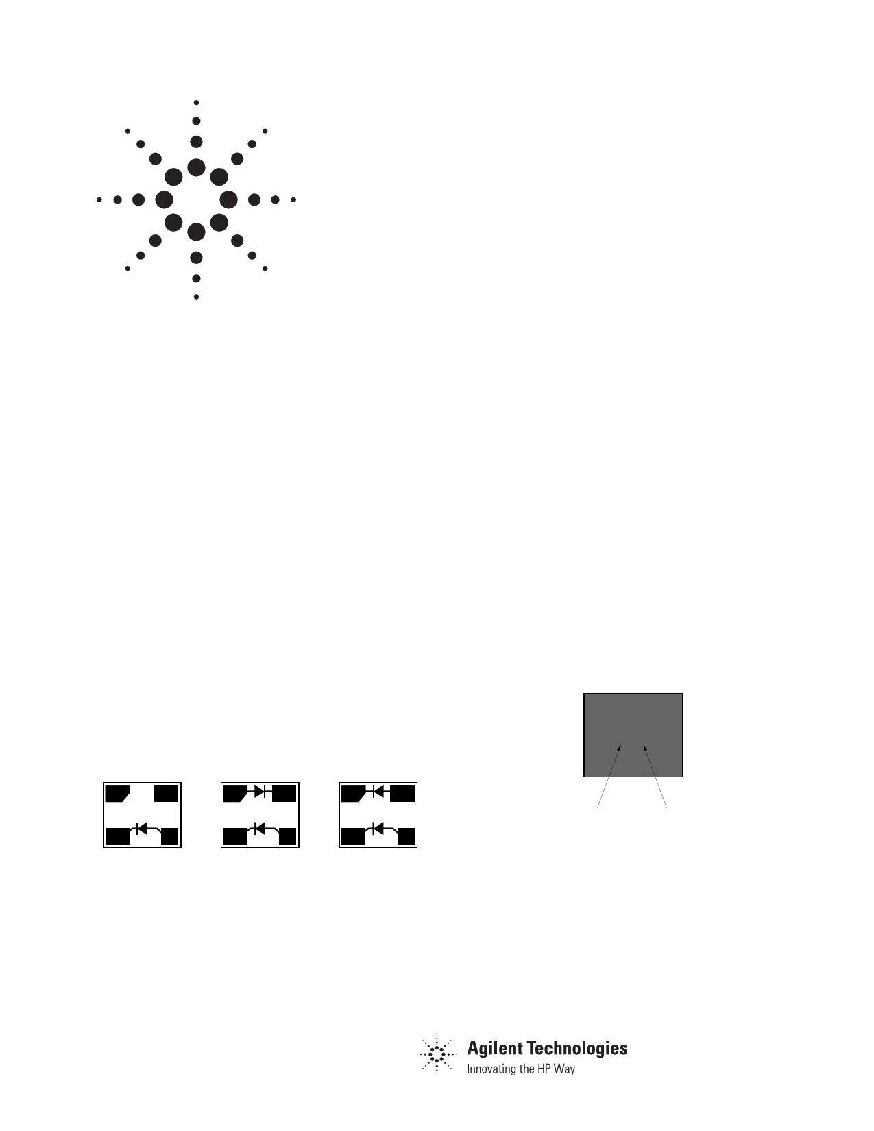
Package Lead Code Identification
(Top View)
Single
Anti-parallel
3 43 4
2 12 1
#0 #2
The HMPS-282x family of diodes
offers the best all-around choice
for most applications, featuring
low series resistance, low forward
voltage at all current levels and
good RF characteristics.
Note that Agilent’s manufacturing
techniques assure that dice found
in pairs and quads are taken from
adjacent sites on the wafer,
assuring the highest degree of
match.
Parallel
34
21
#5
Features
• Surface mount MiniPak package
– low height, 0.7 mm (0.028") max.
– small footprint, 1.75 mm2
(0.0028␣ inch2)
• Better thermal conductivity for
higher power dissipation
• Single and dual versions
• Matched diodes for consistent
performance
• Low turn-on voltage (as low as
0.34␣ V at 1 mA)
• Low FIT (Failure in Time) rate*
• Six-sigma quality level
* For more information, see the Surface
Mount Schottky Reliability Data Sheet.
Pin Connections and
Package Marking
34
AA
21
Product code Date code
Notes:
1. Package marking provides orientation and
identification.
2. See “Electrical Specifications” for
appropriate package marking.
1 page 
Assembly Information
The MiniPak diode is mounted to
the PCB or microstrip board using
the pad pattern shown in
Figure␣ 10.
0.4 0.5 0.4
0.3
0.5
0.3
Figure 10. PCB Pad Layout, MiniPak
(dimensions in mm).
This mounting pad pattern is
satisfactory for most applications.
However, there are applications
where a high degree of isolation is
required between one diode and
the other is required. For such
applications, the mounting pad
pattern of Figure 11 is
recommended.
0.40 mm via hole
(4 places)
0.20
0.8 2.40
0.40
2.60
Figure 11. PCB Pad Layout, High Isolation
MiniPak (dimensions in mm).
This pattern uses four via holes,
connecting the crossed ground
strip pattern to the ground plane
of the board.
SMT Assembly
Reliable assembly of surface
mount components is a complex
process that involves many
material, process, and equipment
factors, including: method of
heating (e.g., IR or vapor phase
reflow, wave soldering, etc.)
circuit board material, conductor
thickness and pattern, type of
solder alloy, and the thermal
conductivity and thermal mass of
components. Components with a
low mass, such as the MiniPak
package, will reach solder reflow
temperatures faster than those
with a greater mass.
Agilent’s diodes have been quali-
fied to the time-temperature
profile shown in Figure 12. This
profile is representative of an IR
reflow type of surface mount
assembly process.
After ramping up from room
temperature, the circuit board
with components attached to it
(held in place with solder paste)
passes through one or more
preheat zones. The preheat zones
increase the temperature of the
board and components to prevent
thermal shock and begin evaporat-
ing solvents from the solder paste.
The reflow zone briefly elevates
the temperature sufficiently to
produce a reflow of the solder.
The rates of change of tempera-
ture for the ramp-up and cool-
down zones are chosen to be low
enough to not cause deformation
of the board or damage to compo-
nents due to thermal shock. The
maximum temperature in the
reflow zone (TMAX) should not
exceed 255°C.
These parameters are typical for a
surface mount assembly process
for Agilent diodes. As a general
guideline, the circuit board and
components should be exposed
only to the minimum temperatures
and times necessary to achieve a
uniform reflow of solder.
350
Peak Temperature
300 Min. 240°C
Max. 255°C
250
221
200
Reflow Time
150
Min. 60 s
Max. 90 s
100
Preheat 130 – 170°C
Min. 60 s
Max. 150 s
50
0
0 30 60 90 120 150 180 210 240 270 300 330 360
TIME (seconds)
Figure 12. Surface Mount Assembly Temperature Profile.
5
5 Page | ||
| Páginas | Total 8 Páginas | |
| PDF Descargar | [ Datasheet HMPS-282X.PDF ] | |
Hoja de datos destacado
| Número de pieza | Descripción | Fabricantes |
| HMPS-282X | MiniPak Surface Mount RF Schottky Barrier Diodes | Hewlett-Packard |
| Número de pieza | Descripción | Fabricantes |
| SLA6805M | High Voltage 3 phase Motor Driver IC. |
Sanken |
| SDC1742 | 12- and 14-Bit Hybrid Synchro / Resolver-to-Digital Converters. |
Analog Devices |
|
DataSheet.es es una pagina web que funciona como un repositorio de manuales o hoja de datos de muchos de los productos más populares, |
| DataSheet.es | 2020 | Privacy Policy | Contacto | Buscar |