|
|
|
PDF D27C256 Data sheet ( Hoja de datos )
| Número de pieza | D27C256 | |
| Descripción | AMD27C256 | |
| Fabricantes | Advanced Micro Devices | |
| Logotipo | ||
Hay una vista previa y un enlace de descarga de D27C256 (archivo pdf) en la parte inferior de esta página. Total 12 Páginas | ||
|
No Preview Available !
www.DataSheet4U.com
FINAL
Am27C256
256 Kilobit (32,768 x 8-Bit) CMOS EPROM
Advanced
Micro
Devices
DISTINCTIVE CHARACTERISTICS
s Fast access time
— 55 ns
s Low power consumption
— 20 µA typical CMOS standby current
s JEDEC-approved pinout
s Single +5 V power supply
s ±10% power supply tolerance available
s 100% Flashrite programming
— Typical programming time of 4 seconds
GENERAL DESCRIPTION
The Am27C256 is a 256K-bit ultraviolet erasable pro-
grammable read-only memory. It is organized as 32K
words by 8 bits per word, operates from a single +5 V
supply, has a static standby mode, and features fast sin-
gle address location programming. Products are avail-
able in windowed ceramic DIP packages as well as plas-
tic one time programmable (OTP) PDIP, TSOP, and
PLCC packages.
Typically, any byte can be accessed in less than 55 ns,
allowing operation with high-performance microproces-
sors without any WAIT states. The Am27C256 offers
separate Output Enable (OE) and Chip Enable (CE)
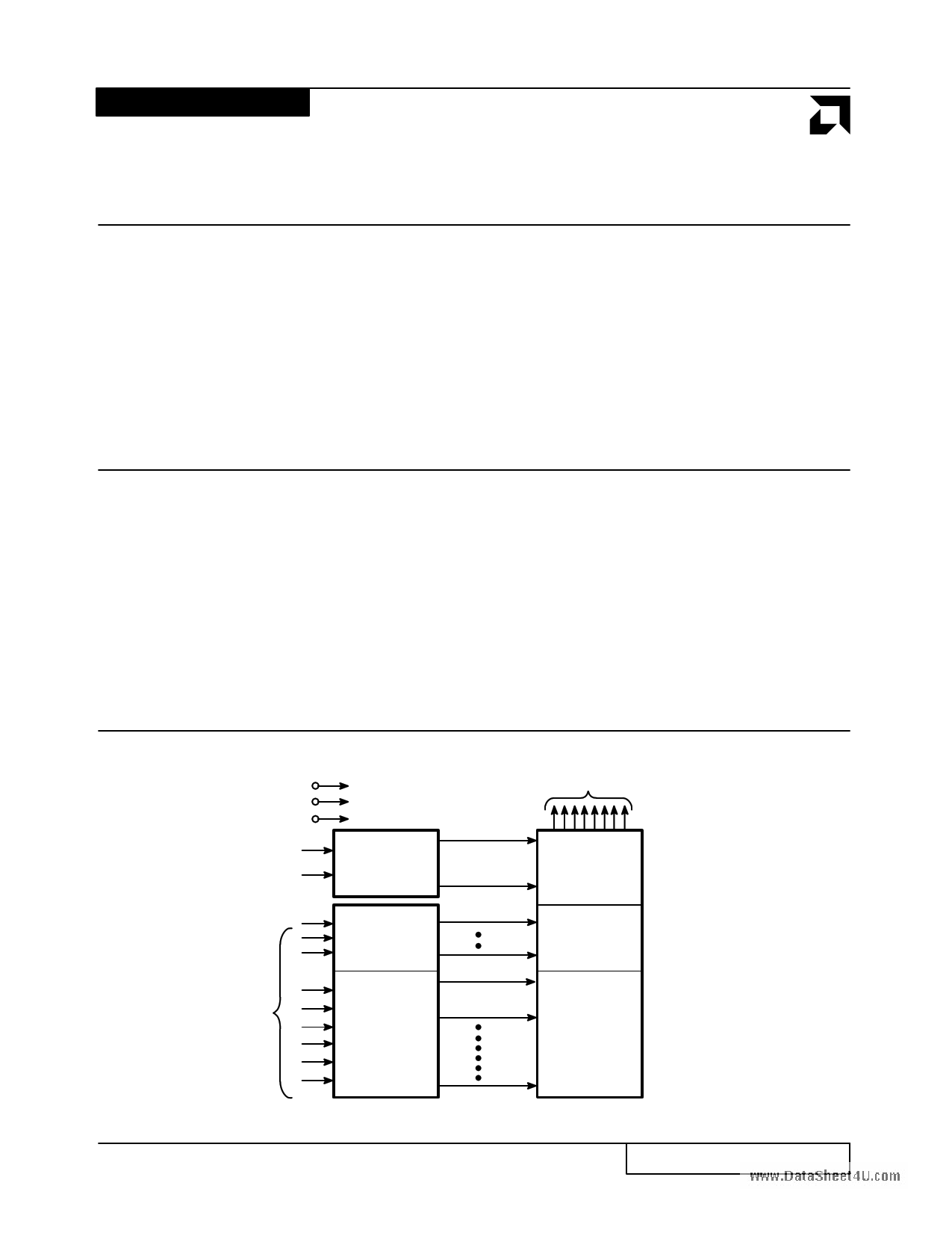
BLOCK DIAGRAM
VCC
VSS
VPP
OE
Output Enable
Chip Enable
CE and
Prog Logic
s Latch-up protected to 100 mA from –1 V to
VCC + 1 V
s High noise immunity
s Versatile features for simple interfacing
— Both CMOS and TTL input/output
compatibility
— Two line control functions
s Standard 28-pin DIP, PDIP, 32-pin TSOP and
PLCC packages
controls, thus eliminating bus contention in a multiple
bus microprocessor system.
AMD’s CMOS process technology provides high speed,
low power, and high noise immunity. Typical power con-
sumption is only 80 mW in active mode, and 100 µW in
standby mode.
All signals are TTL levels, including programming sig-
nals. Bit locations may be programmed singly, in blocks,
or at random. The Am27C256 supports AMD’s Flashrite
programming algorithm (100 µs pulses) resulting in typi-
cal programming time of 4 seconds.
Data Outputs
DQ0–DQ7
Output
Buffers
Y
Decoder
Y
Gating
A0–A14
Address
Inputs
X
Decoder
262,144
Bit Cell
Matrix
2-32
08007H-1
Publication# 08007 Rev. H Amendment /0
Issue Date: May 1995
1 page 
www.DataSheet4U.com
AMD
ORDERING INFORMATION
OTP Products
AMD Standard products are available in several packages and operating ranges. The order number (Valid Combination) is
formed by a combination of:
AM27C256
-55 P C
OPTIONAL PROCESSING
Blank = Standard Processing
TEMPERATURE RANGE
C = Commercial (0°C to +70°C)
I = Industrial (–40°C to + 85°C)
PACKAGE TYPE
P = 28-Pin Plastic DIP (PD 028)
J = 32-Pin Rectangular Plastic Leaded Chip
Carrier (PL 032)
E = 32-Pin TSOP (TS 032)
SPEED OPTION
See Product Selector Guide and Valid Combinations
DEVICE NUMBER
Am27C256
256 Kilobit (32,768 x 8-Bit) CMOS OTP EPROM
Valid Combinations
AM27C256-55
JC, PC, EC
AM27C256-70
AM27C256-90
AM27C256-120
AM27C256-150
JC, PC, EC,
JI, PI, EI
AM27C256-200
AM27C256-255
Valid Combinations
Valid Combinations list configurations planned to be
supported in volume for this device. Consult the lo-
cal AMD sales office to confirm availability of specific
valid combinations and to check on newly released
combinations.
2-36
Am27C256
5 Page 
www.DataSheet4U.com
AMD
SWITCHING TEST CIRCUIT
Device
Under
Test
CL 6.2 kΩ
2.7 kΩ
+5.0 V
Diodes = IN3064
or Equivalent
CL = 100 pF including jig capacitance (30 pF for -55, -70)
SWITCHING TEST WAVEFORM
08007H-8
2.4 V
0.45 V
2.0 V
0.8 V
Input
Test Points
2.0 V
0.8 V
Output
AC Testing: Inputs are driven at 2.4 V for a logic “1”
and 0.45 V for a logic “0”. Input pulse
rise and fall times are ≤ 20 ns.
3V
1.5 V
Test Points
1.5 V
0V
Input
Output
08007H-9
AC Testing: Inputs are driven at 3.0 V for a logic “1”
and 0 V for a logic “0”. Input pulse rise and
fall times are ≤ 20 ns for -55 and -70.
2-42
Am27C256
11 Page | ||
| Páginas | Total 12 Páginas | |
| PDF Descargar | [ Datasheet D27C256.PDF ] | |
Hoja de datos destacado
| Número de pieza | Descripción | Fabricantes |
| D27C256 | AMD27C256 | Advanced Micro Devices |
| Número de pieza | Descripción | Fabricantes |
| SLA6805M | High Voltage 3 phase Motor Driver IC. |
Sanken |
| SDC1742 | 12- and 14-Bit Hybrid Synchro / Resolver-to-Digital Converters. |
Analog Devices |
|
DataSheet.es es una pagina web que funciona como un repositorio de manuales o hoja de datos de muchos de los productos más populares, |
| DataSheet.es | 2020 | Privacy Policy | Contacto | Buscar |