|
|
|
PDF AAT1152 Data sheet ( Hoja de datos )
| Número de pieza | AAT1152 | |
| Descripción | 850kHz 1A Synchronous Buck DC/DC Converter | |
| Fabricantes | Advanced Analogic Technologies | |
| Logotipo | ||
Hay una vista previa y un enlace de descarga de AAT1152 (archivo pdf) en la parte inferior de esta página. Total 18 Páginas | ||
|
No Preview Available !
AAT1152
850kHz 1A Synchronous Buck DC/DC Converter
General Description
The AAT1152 SwitchReg™ is a member of
AnalogicTech™'s Total Power Management™ IC
product family. The Step-down switching converter
is ideal for applications where high efficiency, small
size, and low ripple are critical. Able to deliver 1A
with internal Power MOSFETs, the current-mode
controlled IC provides high efficiency using syn-
chronous rectification. Fully internally compensat-
ed, the AAT1152 simplifies system design and low-
ers external part count.
The AAT1152 features a Power Good (POK) func-
tion which monitors the output, alerting the system
if the output voltage falls out of regulation.
The AAT1152 is available in MSOP-8 package,
rated over -40 to 85°C.
Features
SwitchReg™
• 5.5V max supply input
• Fixed output voltage: 1.1V–4.2V with 100 mV
increment
• 1A output current
• Integrated low on resistance power switches
• Synchronous rectification
• Up to 95% efficiency
• Power Good signal
• Internally compensated current mode control
• High initial accuracy: ±1%
• 850kHz switching frequency
• Constant PWM mode
• Low output ripple with light load
• Internal softstart
• Current limit protection
• Over-Temperature protection
• MSOP-8 package
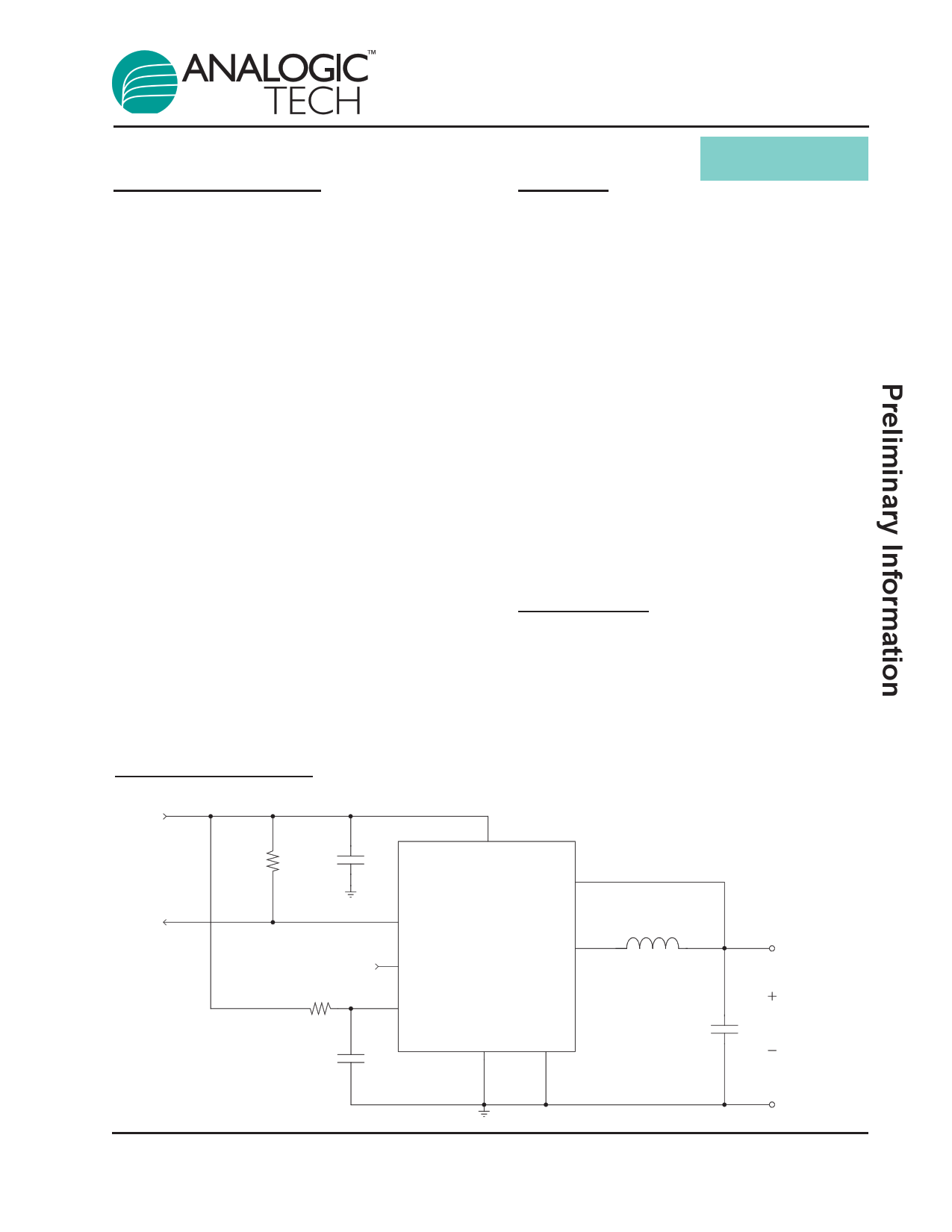
Typical Application
INPUT
100k
10µF
100Ω
0.1µF
Applications
• Computer Peripherals
• Set Top Boxes
• Network Cards
• Cable/DSL Modems
• High efficiency conversion from 5V or 3.3V
supply
VP
AAT1152
POK
ENABLE
FB
LX
VCC
SGND
PGND
4.1µH
47µF
OUTPUT
1152.2003.01.0.9
1
1 page 
AAT1152
850kHz 1A Synchronous Buck DC/DC Converter
Typical Characteristics
High Side RDS(ON) vs. Temperature
170
150
130
110
90
70
-20
2.7V
3.6V
4.2V
5.5V
0 20 40 60 80
Temperature (°C)
100 120
Low Side RDS(ON) vs. Temperature
170
150
130
110 2.7V
90
70
-20
0
3.6V
4.2V
5.5V
20 40 60 80
Temperature (°C)
100
120
130
120
110
100
90
80
2.5
RDS(ON) vs. Input Voltage
High Side
Low Side
3 3.5 4 4.5 5 5.5
Input Voltage (V)
Enable Threshold vs. Input Voltage
1.2
1.1
1
0.9
0.8
0.7
2.5
VEN(H)
VEN(L)
3 3.5 4 4.5 5
Input Voltage (V)
5.5
Oscillator Frequency Variation vs.
Supply Voltage
3.5
2.5
1.5
0.5
-0.5
-1.5
2.5 3 3.5 4 4.5 5 5.5
Supply Voltage (V)
Oscillator Frequency Variation vs. Temperature
VIN=3.6V
10
6
2
-2
-6
-10
-20 0 20 40 60 80 100
Temperature (°C)
1152.2003.01.0.9
5
5 Page 
AAT1152
850kHz 1A Synchronous Buck DC/DC Converter
Power Good
The AAT 1152 features an integrated Power Good
(POK) comparator and open-drain output signal.
The POK pin goes low when the converter’s output
is 12% or more below its nominal regulation volt-
age or when the device is in shutdown. Connect a
pull-up resistor from POK to the converter’s input
or output. Typical resistor pull-up values range
from 100k to 10k.
Inductor
The output inductor is selected to limit the ripple
current to some predetermined value, typically 20-
40% of the full load current at the maximum input
voltage. Manufacturer's specifications list both the
inductor DC current rating, which is a thermal limi-
tation, and the peak current rating, which is deter-
mined by the saturation characteristics. The induc-
tor should not show any appreciable saturation
under all normal load conditions. During over load
and short circuit conditions, the average current in
the inductor can meet or exceed the ILIMIT point of
the AAT1152 without effecting the converter per-
formance. Some inductors may have sufficient
peak and average current ratings yet result in
excessive losses due to a high DCR. Always con-
sider the losses associated with the DCR and its
effect on the total converter efficiency when select-
ing an inductor.
For a 1 Amp load and the ripple set to 30% at the
maximum input voltage, the maximum peak to
peak ripple current is 300 mA. The inductance
value required is 3.9µH.
L
=
VOUT
IO ⋅ k ⋅
F
⋅ 1
-
VOUT
VIN
L
=
1.0A
⋅
1.5V
0.3 ⋅
830kHz
⋅ 1
-
1.5V
4.2V
L = 3.9µH
The factor "k" is the fraction of full load selected for
the ripple current at the maximum input voltage.
The corresponding inductor rms current is:
IRMS =
Io2
+
∆I2
12
≈ Io = 1.0A
∆I is the peak to peak ripple current which is fixed by
the inductor selection above. For a peak to peak cur-
rent of 30% of the full load current the peak current
at full load will be 115% of the full load. The 4.1µH
inductor selected from the Sumida CDRH5D18
series has a 57 mΩ DCR and a 1.95 Amp DC cur-
rent rating. At full load the inductor DC loss is 57mW
which amounts to a 3.8% loss in efficiency.
Input Capacitor
The primary function of the input capacitor is to pro-
vide a low impedance loop for the edges of pulsed
current drawn by the AAT1152. A low ESR/ESL
ceramic capacitor is ideal for this function. To mini-
mize the stray inductance the capacitor should be
placed as close as possible to the IC. This keeps
the high frequency content of the input current
localized, minimizing radiated and conducted EMI
while facilitating optimum performance of the
AAT1152. Ceramic X5R or X7R capacitors are
ideal for this function. The size required will vary
depending on the load, output voltage and input
voltage source impedance characteristics. A typi-
cal value is around 10µF. The input capacitor RMS
current varies with the input voltage and the output
voltage. The equation for the maximum RMS cur-
rent in the input capacitor is:
IRMS = IO ⋅
VO
VIN
⋅ 1 -
VO
VIN
The input capacitor RMS ripple current reaches a
maximum when VIN is two times the output voltage
where it is approximately one half of the load cur-
rent. Losses associated with the input ceramic
capacitor are typically minimal and not an issue. The
proper placement of the input capacitor can be seen
in the reference design layout in figures 5 and 6.
1152.2003.01.0.9
11
11 Page | ||
| Páginas | Total 18 Páginas | |
| PDF Descargar | [ Datasheet AAT1152.PDF ] | |
Hoja de datos destacado
| Número de pieza | Descripción | Fabricantes |
| AAT1150 | 1MHz 1A Step-Down DC/DC Converter | Advanced Analogic Technologies |
| AAT1151 | DC/DC Converter | AAT |
| AAT1152 | 850kHz 1A Synchronous Buck DC/DC Converter | Advanced Analogic Technologies |
| AAT1153 | 2A Step-Down Converter | Advanced Analogic Technologies |
| Número de pieza | Descripción | Fabricantes |
| SLA6805M | High Voltage 3 phase Motor Driver IC. |
Sanken |
| SDC1742 | 12- and 14-Bit Hybrid Synchro / Resolver-to-Digital Converters. |
Analog Devices |
|
DataSheet.es es una pagina web que funciona como un repositorio de manuales o hoja de datos de muchos de los productos más populares, |
| DataSheet.es | 2020 | Privacy Policy | Contacto | Buscar |