|
|
|
PDF IRG4BC20W-S Data sheet ( Hoja de datos )
| Número de pieza | IRG4BC20W-S | |
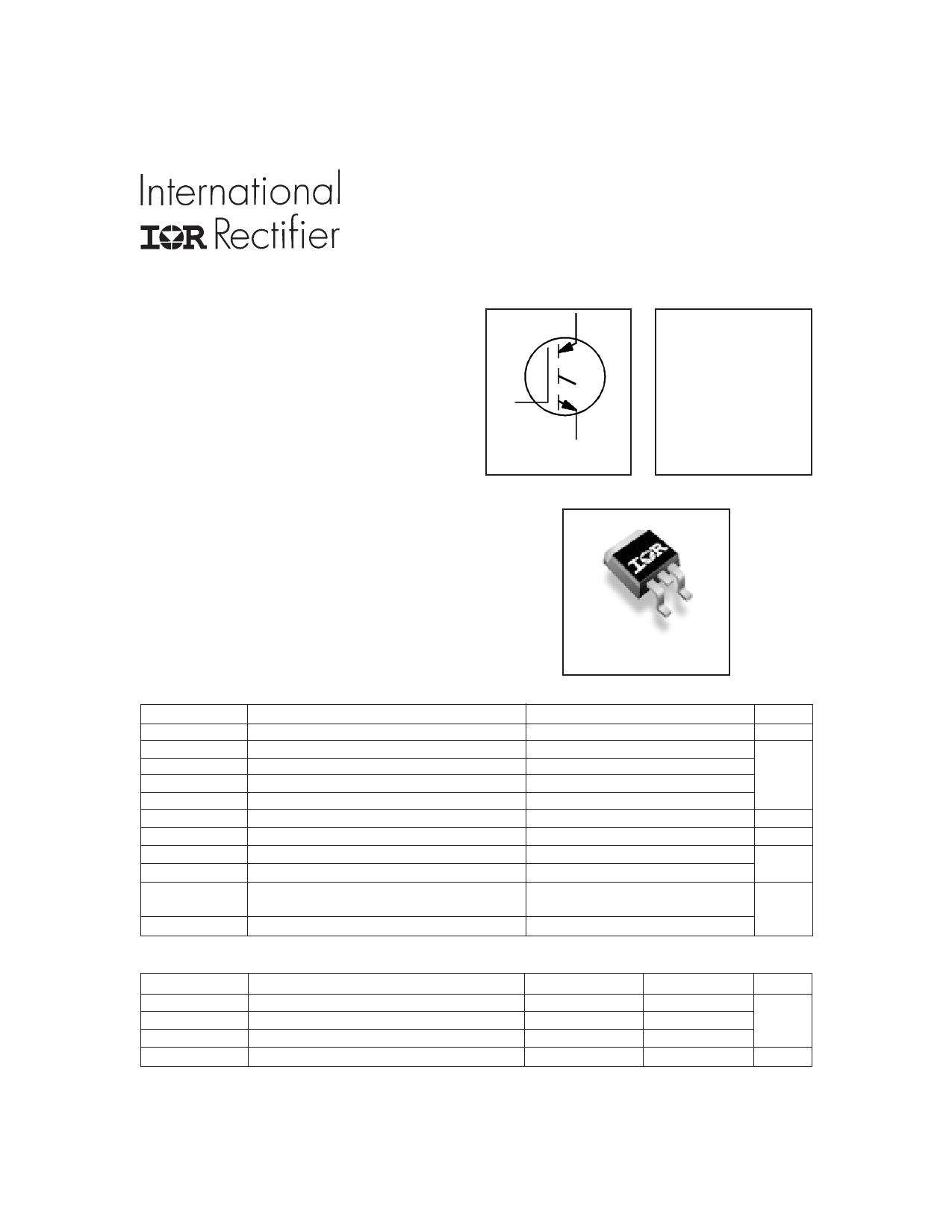
| Descripción | INSULATED GATE BIPOLAR TRANSISTOR | |
| Fabricantes | IRF | |
| Logotipo | ||
Hay una vista previa y un enlace de descarga de IRG4BC20W-S (archivo pdf) en la parte inferior de esta página. Total 9 Páginas | ||
|
No Preview Available !
PD - 94076
INSULATED GATE BIPOLAR TRANSISTOR
IRG4BC20W-S
Features
• Designed expressly for Switch-Mode Power
Supply and PFC (power factor correction)
applications
• Industry-benchmark switching losses improve
efficiency of all power supply topologies
• 50% reduction of Eoff parameter
• Low IGBT conduction losses
• Latest-generation IGBT design and construction offers
tighter parameters distribution, exceptional reliability
Benefits
• Lower switching losses allow more cost-effective
operation than power MOSFETs up to 150kHz
("hard switched" mode)
• Of particular benefit to single-ended converters and
boost PFC topologies 150W and higher
• Low conduction losses and minimal minority-carrier
recombination make these an excellent option for
resonant mode switching as well (up to >>300kHz)
C
G
E
N-channel
VCES = 600V
VCE(on) typ. = 2.16V
@VGE = 15V, IC = 6.5A
D2Pak
Absolute Maximum Ratings
VCES
IC @ TC = 25°C
IC @ TC = 100°C
ICM
ILM
VGE
EARV
PD @ TC = 25°C
PD @ TC = 100°C
TJ
TSTG
Parameter
Collector-to-Emitter Breakdown Voltage
Continuous Collector Current
Continuous Collector Current
Pulsed Collector Current
Clamped Inductive Load Current
Gate-to-Emitter Voltage
Reverse Voltage Avalanche Energy
Maximum Power Dissipation
Maximum Power Dissipation
Operating Junction and
Storage Temperature Range
Soldering Temperature, for 10 seconds
Max.
600
13
6.5
52
52
± 20
200
60
24
-55 to + 150
300 (0.063 in. (1.6mm) from case )
Units
V
A
V
mJ
W
°C
Thermal Resistance
RθJC
RθCS
RθJA
Wt
www.irf.com
Parameter
Junction-to-Case
Case-to-Sink, Flat, Greased Surface
Junction-to-Ambient, typical socket mount
Weight
Typ.
–––
0.5
–––
1.44
Max.
2.1
–––
40
–––
Units
°C/W
g (oz)
1
5/24/00
1 page 
1000
800
VGE = 0V, f = 1MHz
Cies = Cge + Cgc , Cce SHORTED
Cres = Cgc
Coes = Cce + Cgc
600 Cies
400
200
0
1
Coes
Cres
10 100
VCE , Collector-to-Emitter Voltage (V)
Fig. 7 - Typical Capacitance vs.
Collector-to-Emitter Voltage
IRG4BC20W-S
20
VCC = 400V
I C = 6.5A
16
12
8
4
0
0 5 10 15 20 25 30
QG , Total Gate Charge (nC)
Fig. 8 - Typical Gate Charge vs.
Gate-to-Emitter Voltage
0.15 VCC = 480V
VGE = 15V
TJ = 25 °C
IC = 6.5A
0.14
0.13
10 RG = O50hΩm
VGE = 15V
VCC = 480V
1
0.1
IC = 13 A
IC = 6.5 A
IC =3.25 A
0.12
0
10 20 30
RG, Gate Resistance (Ω)
40
50
Fig. 9 - Typical Switching Losses vs. Gate
Resistance
www.irf.com
0.01
-60 -40 -20 0 20 40 60 80 100 120 140 160
TJ, Junction Temperature ( °C )
Fig. 10 - Typical Switching Losses vs.
Junction Temperature
5
5 Page | ||
| Páginas | Total 9 Páginas | |
| PDF Descargar | [ Datasheet IRG4BC20W-S.PDF ] | |
Hoja de datos destacado
| Número de pieza | Descripción | Fabricantes |
| IRG4BC20W-S | INSULATED GATE BIPOLAR TRANSISTOR | IRF |
| Número de pieza | Descripción | Fabricantes |
| SLA6805M | High Voltage 3 phase Motor Driver IC. |
Sanken |
| SDC1742 | 12- and 14-Bit Hybrid Synchro / Resolver-to-Digital Converters. |
Analog Devices |
|
DataSheet.es es una pagina web que funciona como un repositorio de manuales o hoja de datos de muchos de los productos más populares, |
| DataSheet.es | 2020 | Privacy Policy | Contacto | Buscar |