|
|
|
PDF DS1231S Data sheet ( Hoja de datos )
| Número de pieza | DS1231S | |
| Descripción | Power Monitor Chip | |
| Fabricantes | Dallas | |
| Logotipo | ||
Hay una vista previa y un enlace de descarga de DS1231S (archivo pdf) en la parte inferior de esta página. Total 9 Páginas | ||
|
No Preview Available !
DS1231/S
DS1231/S
Power Monitor Chip
FEATURES
• Warns processor of an impending power failure
• Provides time for an orderly shutdown
• Prevents processor from destroying nonvolatile
memory during power transients
• Automatically restarts processor after power is
restored
• Suitable for linear or switching power supplies
• Adjusts to hold time of the power supply
• Supplies necessary signals for processor interface
• Accurate 5% or 10% VCC monitoring
• Replaces power-up reset circuitry
• No external capacitors required
• Optional 16-pin SOIC surface mount package
DESCRIPTION
The DS1231 Power Monitor Chip uses a precise tem-
perature-compensated reference circuit which provides
an orderly shutdown and an automatic restart of a pro-
cessor-based system. A signal warning of an impending
power failure is generated well before regulated DC
voltages go out of specification by monitoring high volt-
age inputs to the power supply regulators. If line isola-
tion is required a UL-approved opto-isolator can be di-
rectly interfaced to the DS1231. The time for processor
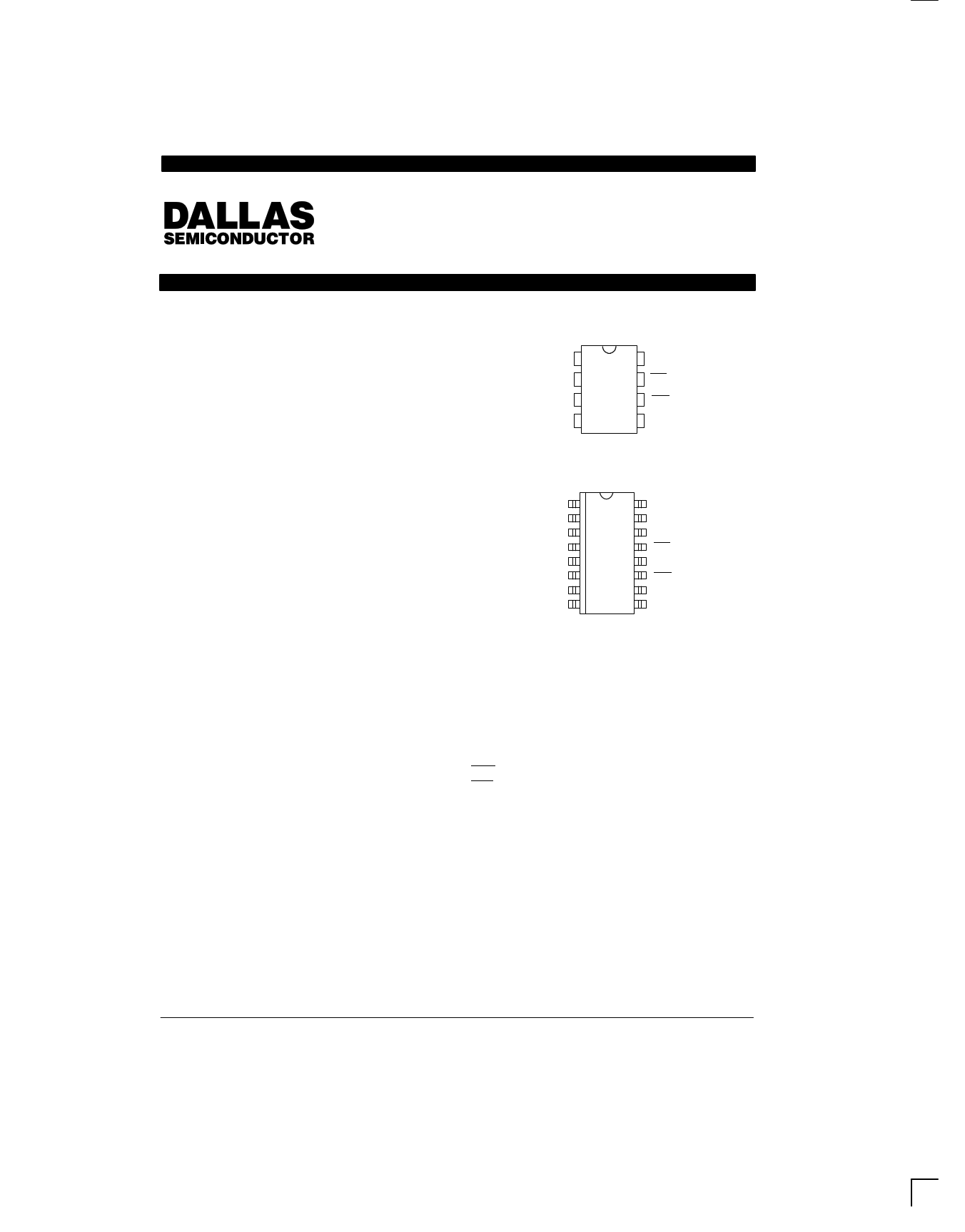
PIN ASSIGNMENT
IN
MODE
TOL
GND
1
2
3
4
8 VCC
7 NMI
6 RST
5 RST
DS1231 8–Pin DIP
(300 MIL)
See Mech. Drawings
Section
NC 1 16 NC
IN 2 15 VCC
NC 3 14 NC
MODE 4 13 NMI
NC 5 12 NC
TOL 6 11 RST
NC 7 10 NC
GND
8
9 RST
DS1231S 16–Pin SOIC
(300 MIL)
See Mech. Drawings
Section
PIN DESCRIPTION
IN – Input
MODE
– Selects input pin characteristics
TOL
GND
– Selects 5% or 10% VCC detect
– Ground
RST
– Reset (Active High)
RST
– Reset (Active Low, open drain)
NMI – Non–Maskable Interrupt
VCC – +5V Supply
NC – No Connections
shutdown is directly proportional to the available
hold-up time of the power supply. Just before the
hold-up time is exhausted, the Power Monitor uncondi-
tionally halts the processor to prevent spurious cycles
by enabling Reset as VCC falls below a selectable 5 or
10 percent threshold. When power returns, the proces-
sor is held inactive until well after power conditions have
stabilized, safeguarding any nonvolatile memory in the
system from inadvertent data changes.
022698 1/9
1 page 
DS1231/S
APPLICATION – MODE PIN CONNECTED TO
GROUND
When the Mode pin is connected to ground, pin 1 is a
current source of 30 µA with a VTP+ of 2.5 volts. Pin 1 is
held below the trip point by a switching device like an
opto-isolator as shown in Figure 6. Determination of the
sense point has the same criteria as discussed in the
previous application. However, determining component
values is significantly different. In this mode, the maxi-
mum dynamic range of the sense point versus desired
trip voltage is primarily determined by the selection of a
zener diode. As an example, if the maximum voltage at
the sense point is 200V and the desired trip point is
150V, then a zener diode of 150V will approximately set
the trip point. This is particularly true if power consump-
tion on the high voltage side of the opto-isolator is not an
issue. However, if power consumption is a concern,
then it is desirable to make the value of R1 high. As the
value of R1 increases, the effect of the LED current in
the opto-isolator starts to affect the IN trip point. This can
be seen from the equation shown in Figure 6. R1 must
also be low enough to allow the opto-isolator to sink the
30 µA of collector current required by pin 1 and still have
enough resistance to keep the maximum current
through the opto-isolator’s LED within data sheet limits.
Figure 7 illustrates how the DS1231 can be interfaced to
the AC power line when the mode pin is grounded.
AC VOLTAGE MONITOR WITH TRANSFORMER ISOLATION Figure 5
VOLTAGE SENSE POINT
DS1231
-10% VCC THRESHOLD
IN VCC +5VDC
MODE
NMI
+5VDC
TOL
RST
TO µ P
GND
RST
NOTE: RST requires a pull–up resister.
022698 5/9
5 Page | ||
| Páginas | Total 9 Páginas | |
| PDF Descargar | [ Datasheet DS1231S.PDF ] | |
Hoja de datos destacado
| Número de pieza | Descripción | Fabricantes |
| DS1231 | Power Monitor Chip | Dallas |
| DS1231S | Power Monitor Chip | Dallas |
| Número de pieza | Descripción | Fabricantes |
| SLA6805M | High Voltage 3 phase Motor Driver IC. |
Sanken |
| SDC1742 | 12- and 14-Bit Hybrid Synchro / Resolver-to-Digital Converters. |
Analog Devices |
|
DataSheet.es es una pagina web que funciona como un repositorio de manuales o hoja de datos de muchos de los productos más populares, |
| DataSheet.es | 2020 | Privacy Policy | Contacto | Buscar |