|
|
|
PDF TL431 Data sheet ( Hoja de datos )
| Número de pieza | TL431 | |
| Descripción | PROGRAMMABLE VOLTAGE REFERENCE | |
| Fabricantes | STMicroelectronics | |
| Logotipo | ||
 1. Precision Shunt Regulator - TI Hay una vista previa y un enlace de descarga de TL431 (archivo pdf) en la parte inferior de esta página. Total 21 Páginas | ||
|
No Preview Available !
TL431
TL432
Programmable voltage reference
Features
■ Adjustable output voltage: 2.5 to 36 V
■ Sink current capability: 1 to 100 mA
■ Typical output impedance: 0.22 Ω
■ 1% and 2% voltage precision
■ Automotive temp. range - 40 °C to +125 °C
Applications
■ Power supply
■ Industrial
■ Automotive
Description
The TL431 and TL432 are programmable shunt
voltage references with guaranteed temperature
stability over the entire operating temperature
range. The device temperature range is extended
for the automotive version from -40 °C up to
+125 °C. The output voltage can be set to any
value between 2.5 and 36 V with two external
resistors. The TL431 and TL432 operate with a
wide current range from 1 to 100 mA with a typical
dynamic impedance of 0.22 Ω.
Datasheet − production data
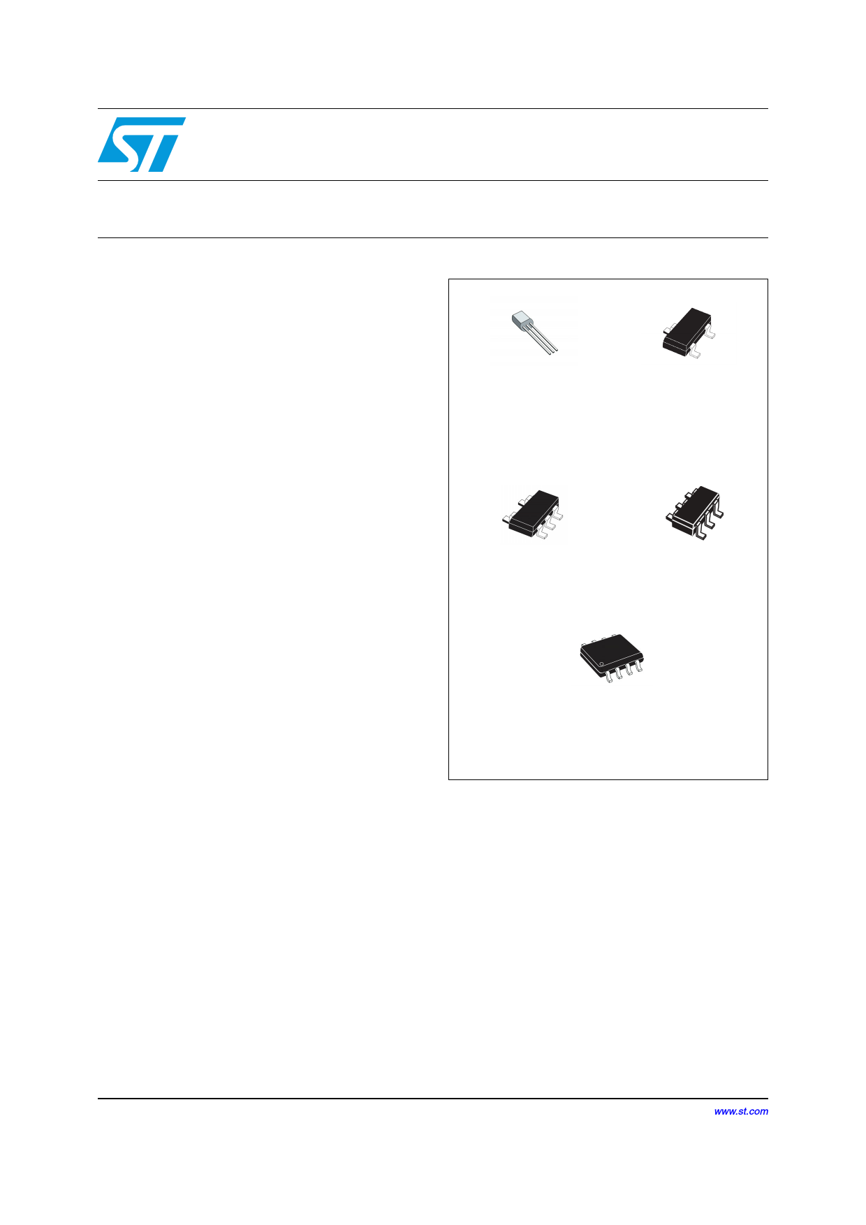
Z
TO-92
(Plastic package)
L
SOT23-3
L
SOT23-5
C
SOT323-6
D
SO-8
(Batwing plastic micropackage)
December 2012
This is information on a product in full production.
Doc ID 4467 Rev 11
1/21
www.st.com
21
1 page 
TL431, TL432
3 Electrical characteristics
Electrical characteristics
Table 3.
Symbol
TL431C (Tamb = 25° C unless otherwise specified)
Parameter
TL431C
Min. Typ. Max.
TL431AC
Min. Typ. Max.
Unit
Reference input voltage
Vref VKA = Vref, Ik = 10 mA, Tamb = 25° C
Tmin ≤ Tamb ≤ Tmax
2.44 2.495 2.55 2.47 2.495 2.52 V
2.423
2.567 2.453
2.537
ΔVref
Reference input voltage deviation over temperature
range (1)
VKA = Vref, Ik = 10 mA, Tmin ≤ Tamb ≤ Tmax
3 17
mV
3 15
Ratio of change in reference input voltage to change
Δ----V---r--e---f
ΔVka
in cathode to anode voltage
Ik = 10 mA - ΔVKA = 10 V to Vref
ΔVKA = 36 V to 10 V
-2.7 -1.4
-2 -1
-2.7 -1.4
-2 -1
mV/V
Reference input current
Iref
Ik = 10 mA, R1 = 10 kΩ, R2 = ∞
Tamb = 25° C
Tmin ≤ Tamb ≤ Tmax
1.8 4
5.2
1.8 4
5.2
µA
Reference input current deviation over temperature
range
ΔIref Ik = 10 mA, R1 = 10 kΩ, R2 =∞
Tmin ≤ Tamb ≤ Tmax
0.4 1.2
0.4 1.2
µA
Minimum cathode current for regulation
Imin VKA = Vref
0.5 1
mA
0.5 0.6
Ioff
⏐ZKA⏐
Off-state cathode current
Dynamic impedance (2)
VKA = Vref, Δ Ik = 1 to 100 mA, f ≤ 1 kHZ
2.6 1000
0.22 0.5
2.6 1000 nA
Ω
0.22 0.5
1. See definition of Section 3.1: Reference input voltage deviation over temperature range.
2. The dynamic impedance is defined as |ZKA| = Δ-----V----K----A--
ΔIk
Doc ID 4467 Rev 11
5/21
5 Page 
TL431, TL432
4 Package mechanical data
Package mechanical data
In order to meet environmental requirements, ST offers these devices in different grades of
ECOPACK® packages, depending on their level of environmental compliance. ECOPACK®
specifications, grade definitions and product status are available at: www.st.com.
ECOPACK® is an ST trademark.
Doc ID 4467 Rev 11
11/21
11 Page | ||
| Páginas | Total 21 Páginas | |
| PDF Descargar | [ Datasheet TL431.PDF ] | |
Hoja de datos destacado
| Número de pieza | Descripción | Fabricantes |
| TL430 | Adjustable Shunt Regulators (Rev. D) | Texas Instruments |
| TL431 | ADJUSTABLE PRECISION SHUNT REGULATOR | Diodes |
| TL431 | PROGRAMMABLE PRECISION REFERENCES | Motorola Semiconductors |
| TL431 | PROGRAMMABLE PRECISION REFERENCES | ON Semiconductor |
| Número de pieza | Descripción | Fabricantes |
| SLA6805M | High Voltage 3 phase Motor Driver IC. |
Sanken |
| SDC1742 | 12- and 14-Bit Hybrid Synchro / Resolver-to-Digital Converters. |
Analog Devices |
|
DataSheet.es es una pagina web que funciona como un repositorio de manuales o hoja de datos de muchos de los productos más populares, |
| DataSheet.es | 2020 | Privacy Policy | Contacto | Buscar |