|
|
|
PDF SC431CS-1 Data sheet ( Hoja de datos )
| Número de pieza | SC431CS-1 | |
| Descripción | ADJUSTABLE SHUNT REGULATOR | |
| Fabricantes | Semtech Corporation | |
| Logotipo | ||
Hay una vista previa y un enlace de descarga de SC431CS-1 (archivo pdf) en la parte inferior de esta página. Total 6 Páginas | ||
|
No Preview Available !
ADJUSTABLE SHUNT REGULATOR
SC431
April 13, 1998
TEL:805-498-2111 FAX:805-498-3804 WEB:http://www.semtech.com
DESCRIPTION
The SC431 is a three terminal adjustable shunt regula-
tor with thermal stability guaranteed over temperature.
The output voltage can be adjusted to any value from
2.5V (VREF) to 36V with two external resistors. The
SC431 has a typical dynamic output impedance of
0.25Ω. Active output circuitry provides a very sharp
turn on characteristic, making the SC431 an excellent
replacement for zener diodes.
The SC431 shunt regulator is available in three voltage
tolerances (0.5%, 1.0% and 2.0%) and three package
options (SOT-23-3, SO-8 and TO-92). The three volt-
age tolerances allow the designer the opportunity to
select the proper cost/tolerance for their application.
FEATURES
• Wide operating current range 100µA to 150mA
• Low dynamic output impedance 0.25 Ω typ.
• Trimmed bandgap design + 0.5%
• Alternate for TL431, LM431 & AS431
APPLICATIONS
• Linear Regulators
• Adjustable Supplies
• Switching Power Supplies
• Battery Operated Computers
• Instrumentation
• Computer Disk Drives
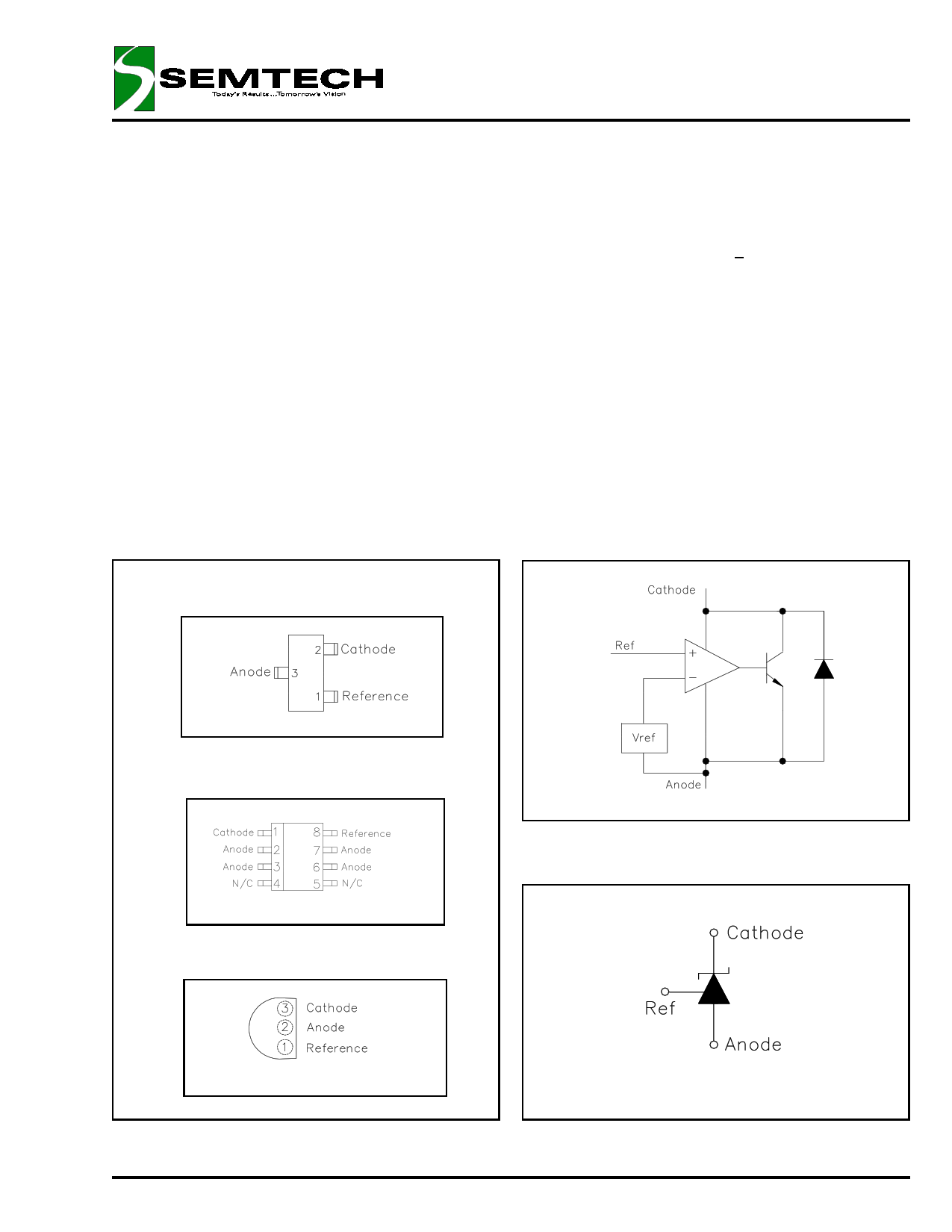
PIN CONFIGURATIONS
SOT-23 -3 Lead (Top View)
BLOCK DIAGRAM
SOIC 8 Lead (Top View)
TO-92 (Top View)
SYMBOL DIAGRAM
© 1998 SEMTECH CORP.
1
652 MITCHELL ROAD NEWBURY PARK CA 91320
1 page 
ADJUSTABLE SHUNT REGULATOR
SC431
April 13, 1998
TYPICAL CHARACTERISTICS (Cont.)
Small-Signal Gain and Phase Shift
vs. Frequency
80
70
60
50
40
30
20
10
0
-10
-20
1.0E+02
1.0E+03
1.0E+04
f (Hz)
IZ = 10mA
TA = 25°C
-180
-225
-270
-315
-360
-405
-450
-495
-540
-585
1.0E+05
-630
1.0E+06
100
IZ = 10mA
TA = 25°C
10
Reference Impedance
vs. Frequency
Test Circuit For Small-Signal
Gain and Phase Shift
1
0.1
0.01
1.0E+03
1.0E+04
1.0E+05
f (Hz)
APPLICATION CIRCUIT
1.0E+06
1.0E+07
Notes for Application Circuit:
1) Set VOUT according to the following equation:
VOUT
= VREF
1 +
R1
R2
+
IREF
R1
2) Choose the value for R as follows:
• The maximum limit for R should be such that the
cathode current, IZ, is greater than the minimum
operating current (100µA) at VIN(min).
• The minimum limit for R should be such that IZ
does not exceed 150mA under all load conditions,
and the instantaneous turn-on value for IZ does not
exceed 200mA. Both of the following conditions
must be met:
R min
≥
VIN (max)
200 mA
(to limit instantaneous turn-on IZ)
R min
≥ VIN(max) − VOUT
IOUT (min) + 150 mA
(to limit IZ under normal
operating conditions)
© 1998 SEMTECH CORP.
5
652 MITCHELL ROAD NEWBURY PARK CA 91320
5 Page | ||
| Páginas | Total 6 Páginas | |
| PDF Descargar | [ Datasheet SC431CS-1.PDF ] | |
Hoja de datos destacado
| Número de pieza | Descripción | Fabricantes |
| SC431CS-1 | ADJUSTABLE SHUNT REGULATOR | Semtech Corporation |
| SC431CS-2 | ADJUSTABLE SHUNT REGULATOR | Semtech Corporation |
| SC431CS-5 | ADJUSTABLE SHUNT REGULATOR | Semtech Corporation |
| Número de pieza | Descripción | Fabricantes |
| SLA6805M | High Voltage 3 phase Motor Driver IC. |
Sanken |
| SDC1742 | 12- and 14-Bit Hybrid Synchro / Resolver-to-Digital Converters. |
Analog Devices |
|
DataSheet.es es una pagina web que funciona como un repositorio de manuales o hoja de datos de muchos de los productos más populares, |
| DataSheet.es | 2020 | Privacy Policy | Contacto | Buscar |