|
|
|
PDF EL2244C Data sheet ( Hoja de datos )
| Número de pieza | EL2244C | |
| Descripción | Dual/Quad Low-Power 120MHz Unity-Gain Stable Op Amp | |
| Fabricantes | Elantec Semiconductor | |
| Logotipo | ||
Hay una vista previa y un enlace de descarga de EL2244C (archivo pdf) en la parte inferior de esta página. Total 16 Páginas | ||
|
No Preview Available !
EL2244C, EL2444C
Dual/Quad Low-Power 120MHz Unity-Gain Stable Op Amp
Features
• 120MHz gain-bandwidth product
• Unity-gain stable
• Low supply current (per amplifier)
- 5.2mA at VS = ±15V
• Wide supply range - ±2V to ±18V
dual-supply, 2.5V to 36V single-
supply
• High slew rate - 325V/µs
• Fast settling - 80ns to 0.1% for a
10V step
• Low differential gain - 0.04% at
AV = +2, RL = 150¾
• Low differential phase - 0.15° at
AV = +2, RL = 150Ω
• Stable w/ unlimited capacitive load
• Wide output voltage swing -
±13.6V with VS = ±15V, RL =
1000Ω, 3.8V/0.3V with VS = +5V,
RL = 500Ω
• Low cost, enhanced replacement
for the AD827
andLT1229/LT1230
Applications
• Video amplifier
• Single-supply amplifier
• Active filters/integrators
• High-speed sample-and-hold
• High-speed signal processing
• ADC/DAC buffer
• Pulse/RF amplifier
• Pin diode receiver
• Log amplifier
• Photo multiplier amplifier
• Difference amplifier
Ordering Information
Part No.
EL2244CN
EL2244CS
EL2444CN
EL2444CS
EL2444CM
Temp. Range
-40°C to +85°C
-40°C to +85°C
-40°C to +85°C
-40°C to +85°C
-40°C to +85°C
Package
8-Pin P-DIP
8-Lead SO
14-Pin P-DIP
14-Lead SO
16-Lead SOL
Outline #
MDP0031
MDP0027
MDP0031
MDP0027
MDP0027
General Description
The EL2244C/EL2444C are dual and quad versions of the popular
EL2044C. They are high speed, low power, low cost monolithic oper-
ational amplifiers built on Elantec's proprietary complementary
bipolar process. The EL2244C/EL2444C are unity-gain stable and
feature a 325V/µs slew rate and 120MHz gain-bandwidth product
while requiring only 5.2mA of supply current per amplifier.
The power supply operating range of the EL2244C/EL2444C is from
±18V down to as little as ±2V. For single-supply operation, the
EL2244C/EL2444C operate from 36V down to as little as 2.5V. The
excellent power supply operating range of the EL2244C/EL2444C
makes them an obvious choice for applications on a single +5V or
+3V supply.
The EL2244C/EL2444C also feature an extremely wide output volt-
age swing of ±13.6V with VS = ±15V and RL = 1000Ω. At ±5V,
output voltage swing is a wide ±3.8V with RL = 500Ω and ±3.2V with
RL = 150Ω. Furthermore, for single-supply operation at +5V, output
voltage swing is an excellent 0.3V to 3.8V with RL = 500Ω.
At a gain of +1, the EL2244C/EL2444C have a -3dB bandwidth of
120MHz with a phase margin of 50°. They can drive unlimited load
capacitance, andwww.DataSheet.net/ because of their conventional voltage-feedback
topology, the EL2244C/EL2444C allow the use of reactive or non-lin-
ear elements in their feedback network. This versatility combined with
low cost and 75mA of output-current drive make the
EL2244C/EL2444C an ideal choice for price-sensitive applications
requiring low power and high speed.
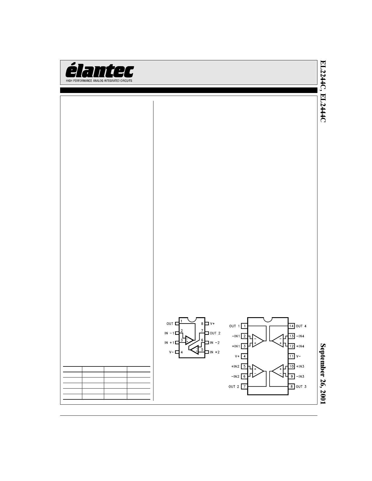
Connection Diagrams
EL2244CN/CS
Dual
EL2444CN/CS
Quad
Note: All information contained in this data sheet has been carefully checked and is believed to be accurate as of the date of publication; however, this data sheet cannot be a “controlled document”. Current revisions, if any, to these
specifications are maintained at the factory and are available upon your request. We recommend checking the revision level before finalization of your design documentation.
© 2001 Elantec Semiconductor, Inc.
Datasheet pdf - http://www.DataSheet4U.co.kr/
1 page 
EL2244C, EL2444C
Dual/Quad Low-Power 120MHz Unity-Gain Stable Op Amp
Typical Performance Curves
Non-Inverting
Frequency Response
Inverting Frequency Response
Frequency Response for
Various Load Resistances
Open-Loop Gain and
Phase vs Frequency
Output Voltage Swing
vs Frequency
Equivalent Input Noise
CMRR, PSRR and Closed-Loop
Output Resistance vs Frequency
www.DataSheet.net/
2nd and 3rd Harmonic
Distortion vs Frequency
Settling Time vs
Output Voltage Change
Supply Current vs
Supply Voltage
Common-Mode Input Range
vs Supply Voltage
Output Voltage Range
vs Supply Voltage
5
Datasheet pdf - http://www.DataSheet4U.co.kr/
5 Page 
EL2244C, EL2444C
Dual/Quad Low-Power 120MHz Unity-Gain Stable Op Amp
bandwidth product divided by the noise gain of the cir-
cuit. For gains less than 4, higher-order poles in the
amplifiers' transfer function contribute to even higher
closed loop bandwidths. For example, the
EL2244C/EL2444C have a -3dB bandwidth of 120MHz
at a gain of +1, dropping to 60MHz at a gain of +2. It is
important to note that the EL2244C/EL2444C have been
designed so that this “extra” bandwidth in low-gain
applications does not come at the expense of stability.
As seen in the typical performance curves, the
EL2244C/EL2444C in a gain of +1 only exhibit 1.0dB
of peaking with a 1000Ω load.
Video Performance
An industry-standard method of measuring the video
distortion of components such as the EL2244C/
EL2444C is to measure the amount of differential gain
(dG) and differential phase (dP) that they introduce. To
make these measurements, a 0.286VPP (40 IRE) signal is
applied to the device with 0V DC offset (0 IRE) at either
3.58MHz for NTSC or 4.43MHz for PAL. A second
measurement is then made at 0.714V DC offset (100
IRE). Differential gain is a measure of the change in
amplitude of the sine wave, and is measured in percent.
Differential phase is a measure of the change in phase,
and is measured in degrees.
For signal transmission and distribution, a back-termi-
nated cable (75Ω in series at the drive end, and 75Ω to
ground at the receiving end) is preferred since the
impedance match at both ends will absorb any reflec-
tions. However, when double termination is used, the
received signal is halved; therefore a gain of 2 configu-
ration is typically used to compensate for the
attenuation.
The EL2244C/EL2444C have been designed as an eco-
nomical solution for applications requiring low video
distortion. They have been thoroughly characterized for
video performance in the topology described above, and
the results have been included as typical dG and dP
specifications and as typical performance curves. In a
gain of +2, driving 150Ω, with standard video test levels
at the input, the EL2244C/EL2444C exhibit dG and dP
of only 0.04% and 0.15° at NTSC and PAL. Because dG
and dP can vary with different DC offsets, the video per-
formance of the EL2244C/EL2444C has been
characterized over the entire DC offset range from -
0.714V to +0.714V. For more information, refer to the
curves of dG and dP vs DC Input Offset.
Output Drive Capability
The EL2244C/EL2444C have been designed to drive
low impedance loads. They can easily drive 6VPP into a
150¾ load. This high output drive capability makes the
EL2244C/EL2444C an ideal choice for RF, IF and video
applications. Furthermore, the current drive of the
EL2244C/EL2444C remains a minimum of 35 mA at
low temperatures. The EL2244C/EL2444C are current-
limited at the output, allowing it to withstand shorts to
ground. However, power dissipation with the output
shorted can be in excess of the power-dissipation capa-
bilities of the package.
Capacitive Loads
For ease of use, the EL2244C/EL2444C have been
designed to drive any capacitive load. However, the
EL2244C/EL2444C remain stable by automatically
reducing their gain-bandwidth product as capacitive
www.DataSheet.net/
load increases. Therefore, for maximum bandwidth,
capacitive loads should be reduced as much as possible
or isolated via a series output resistor (Rs). Similarly,
coax lines can be driven, but best AC performance is
obtained when they are terminated with their character-
istic impedance so that the capacitance of the coaxial
cable will not add to the capacitive load seen by the
amplifier. Although stable with all capacitive loads,
some peaking still occurs as load capacitance increases.
A series resistor at the output of the EL2244C/EL2444C
can be used to reduce this peaking and further improve
stability.
Printed-Circuit Layout
The EL2244C/EL2444C are well behaved, and easy to
apply in most applications. However, a few simple tech-
niques will help assure rapid, high quality results. As
with any high-frequency device, good PCB layout is
necessary for optimum performance. Ground-plane con-
struction is highly recommended, as is good power
supply bypassing. A 0.1 µF ceramic capacitor is recom-
mended for bypassing both supplies. Lead lengths
should be as short as possible, and bypass capacitors
should be as close to the device pins as possible. For
11
Datasheet pdf - http://www.DataSheet4U.co.kr/
11 Page | ||
| Páginas | Total 16 Páginas | |
| PDF Descargar | [ Datasheet EL2244C.PDF ] | |
Hoja de datos destacado
| Número de pieza | Descripción | Fabricantes |
| EL2244 | Dual/Quad Low-Power 120MHz Unity-Gain Stable Op Amp | Elantec Semiconductor |
| EL2244C | Dual/Quad Low-Power 120MHz Unity-Gain Stable Op Amp | Elantec Semiconductor |
| EL2244CN | Dual/Quad Low-Power 120MHz Unity-Gain Stable Op Amp | Elantec Semiconductor |
| EL2244CS | Dual/Quad Low-Power 120MHz Unity-Gain Stable Op Amp | Elantec Semiconductor |
| Número de pieza | Descripción | Fabricantes |
| SLA6805M | High Voltage 3 phase Motor Driver IC. |
Sanken |
| SDC1742 | 12- and 14-Bit Hybrid Synchro / Resolver-to-Digital Converters. |
Analog Devices |
|
DataSheet.es es una pagina web que funciona como un repositorio de manuales o hoja de datos de muchos de los productos más populares, |
| DataSheet.es | 2020 | Privacy Policy | Contacto | Buscar |