|
|
|
PDF AAT3680ITP-4.1-T1 Data sheet ( Hoja de datos )
| Número de pieza | AAT3680ITP-4.1-T1 | |
| Descripción | Lithium-Ion Linear Battery Charge Controller | |
| Fabricantes | Advanced Analogic Technologies | |
| Logotipo | ||
Hay una vista previa y un enlace de descarga de AAT3680ITP-4.1-T1 (archivo pdf) en la parte inferior de esta página. Total 18 Páginas | ||
|
No Preview Available !
AAT3680
Lithium-Ion Linear Battery Charge Controller
General Description
The AAT3680 BatteryManager™ is a member of
AnalogicTech's Total Power Management IC™
family. This device is an advanced Lithium-Ion (Li-
Ion) battery charge and management IC, specifi-
cally designed for low cost compact portable appli-
cations. In a single 8-pin package, the AAT3680
precisely regulates battery charge voltage and
charge current. This device is capable of two trick-
le charge current levels controlled by one external
pin. Battery charge temperature and charge state
are carefully monitored for fault conditions. In the
event of an over current, short circuit or over tem-
perature failure, the device will automatically shut
down, thus protecting the charging device and the
battery under charge. A battery charge state mon-
itor output pin is provided to indicate the battery
charge status though a display LED. The battery
charge status output is a serial interface which may
also be read by a system microcontroller.
The AAT3680 is available in an 8-pin MSOP or 12-
pin TSOPJW package, specified over -20 to 70°C
range.
Features BatteryManager™
• 4.5V to 15V Input voltage range
• 1% Accurate Preset Voltages: 4.1V, 4.2V,
8.2V, 8.4V
• Low operation current, typically 0.5mA
• Programmable Charge Current
• Automatic recharge sequencing
• Battery temperature monitoring
• Deep discharge cell conditioning
• Fast trickle charge option with thermal over-ride
• Full battery charge auto turn off / sleep mode
• Over voltage, current and temperature
protection
• Power on reset
• LED Charge Status Output or System
Microcontroller serial interface
• Temperature range -20 to 70°C
• 8 pin MSOP, 12 pin TSOPJW package
Applications
• Cellular Phones
• Personal Digital Assistants (PDA's)
• Desktop Chargers
• USB Chargers
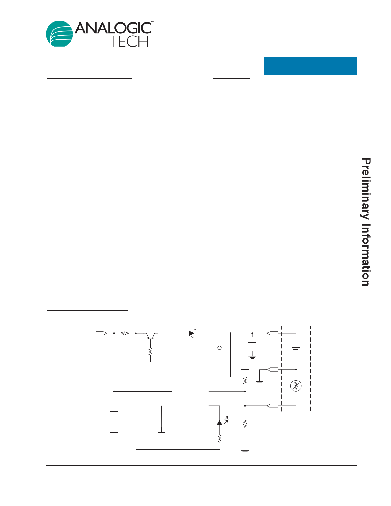
Typical Application
RSENSE
Q1
0.2Ω
FZT788B
VP
C1
4.7µF
R1
2.5k
DRV
T2X
CSI BAT
AAT3680
VP TS
VSS
STAT
D1
R2
1k
BATT+
C2
10µF
VP
RT1
BATT-
TEMP
Battery
RT2 Pack
3680.2003.4.0.91
1
1 page 
AAT3680
Lithium-Ion Linear Battery Charge Controller
Functional Block Diagram
T2X
CSI
BAT
TS
VP
Microcontroller
Read Enable
2x Trickle
Charge
Control
Current Loop
Error Amp
Loop Select
MUX Driver
VREF
Voltage Loop
Error Amp
Charge Status
Logic Control
Voltage
Comparator
Microcontroller
Status Generator
MUX
LED Signal
Generator
Temperature Sense
Comparator
Power-On
Reset
Under
Voltage
Lock Out
Over Current /
Short Circuit
Protection
DRV
STAT
VSS
Functional Description
The AAT3680 is a Linear Charge Controller
designed for one and two cell Lithium Ion or
Lithium Polymer batteries. It is a full-featured bat-
tery management system IC with multiple levels of
power savings, system communication and protec-
tion integrated inside. Refer to the block diagram
and flow chart in this section.
Cell Preconditioning
Before starting charging, the AAT3680 checks sev-
eral conditions in order to maintain a safe charging
environment. The input supply must be above the
minimum operating voltage, or undervoltage lock-
out threshold (VUVLO), for the charging sequence to
begin. Also, the cell temperature, as reported by a
thermistor connected to TS pin, must be within the
proper window for safe charging. When these con-
ditions have been met, and a battery is connected
to the BAT pin, the AAT3680 checks the state of the
battery. If the cell voltage is below VMIN, the
AAT3680 begins preconditioning the cell. This is
performed by charging the cell with 10% of the pro-
grammed constant-current amount. For example if
the programmed charge current is 500mA, then the
preconditioning mode (trickle charge) current will be
50mA. Cell preconditioning is a safety precaution
for deeply discharged cells, and furthermore, limits
the power dissipation in the pass transistor when
the voltage across the device is largest. The
AAT3680 features an optional T2X mode, which
allows faster trickle-charging at approximately two
times the default rate. This mode is selected by
connecting the T2X pin to VSS. If an over-tempera-
ture fault is triggered, the fast trickle-charge will be
latched off, and the AAT3680 will continue at the
default 10% charge current.
Constant Current Charging
The cell preconditioning continues until the voltage
on the BAT pin reaches VMIN. At this point, the
AAT3680 begins constant-current charging (fast
charging). Current level for this mode is pro-
grammed using a current sense resistor RSENSE
between VP and CSI pins. The CSI pin monitors the
voltage across RSENSE to provide feedback for the
current control loop. The AAT3680 remains in con-
stant current charge mode until the battery reaches
the voltage regulation point, VCH.
3680.2003.4.0.91
5
5 Page 
AAT3680
Lithium-Ion Linear Battery Charge Controller
PD = (VP(MAX) - VCS - VD - VMIN) · ICHARGE(REG)
PD = (5.5V - 0.1V - 0.4V - 3.1V) · 750mA
PD = 1.4W
2. The next step is to determine which size package
is needed to keep the junction temperature below its
rated value, TJ(MAX). Using this value, and the maxi-
mum ambient temperature inside the system TA(MAX),
calculate the thermal resistance RθJA required:
RθJA
=
(TJ(MAX) - TA(MAX))
PD
RθJA
=
(150 -
1.4
40)
RθJA = 79°C/W
It is recommended to choose a package with a lower
RθJA than the number calculated above. A SOT223
package would be an acceptable choice, as it has an
RθJA of 62.5°C/W when mounted to a PCB with ade-
quately sized copper pad soldered to the heat tab.
3. Choose a drain-source (VDS) voltage rating
greater than the input voltage. In this example, VP
is 5.0V, so a 12V device is acceptable.
4. Choose a MOSFET with a drain current rating at
least 50% greater than the programmed
ICHARGE(REG) value. In this example we would
select a device with at least 1.125A rating.
5. Calculate the required threshold voltage to deliv-
er ICHARGE(REG):
VGS = (VCS + VOL@DRV) - VP(MIN)
VGS = (0.1V + 0.1V) - 4.5V
VGS = -4.3V
where VGS is the available gate to source voltage pro-
vided by the AAT3680, VCS is the voltage across the
sense resistor, VOL@DRV is the rated low voltage at the
DRV pin, and VP(MIN) is the worst case input voltage
(assuming 10% tolerance on the 5V supply). Choose
a MOSFET device with sufficiently low VGS(TH) so the
device will conduct the desired ICHARGE(REG).
6. Calculate the worst case maximum allowable
RDS(ON) at worst case VGS voltage:
RDS(ON)
=
(VP(MIN) - VCS(MAX) -
ICHARGE(REG)
VBAT(MAX))
RDS(ON)
=
(4.5V
-
0.11V -
0.75A
4.242V)
RDS(ON) = 197mΩ
Select a P-Channel Power MOSFET with RDS(ON)
lower than 197mΩ at VGS = -4.3V.
In summary, select a P-Channel MOSFET with ratings
VDS ≥ 12V, RθJA ≤ 79°C/W and RDS(ON) ≥ 197mΩ at
VGS = -4.3V in a SOT223 (or better thermal) package.
Q1
RSENSE
RFD10P03L
0.2Ω
VP
R4
100k
R1
1k
BATT+
C2
10µF
DRV
T2X
VP BATT-
CSI BAT
AAT3680
VP TS
RT1
C1
4.7µF
VSS
STAT
D1
TEMP
Battery
RT2 Pack
R2
1k
Figure 5: Typical Applications Schematic Using P-Channel Power MOSFET
3680.2003.4.0.91
11
11 Page | ||
| Páginas | Total 18 Páginas | |
| PDF Descargar | [ Datasheet AAT3680ITP-4.1-T1.PDF ] | |
Hoja de datos destacado
| Número de pieza | Descripción | Fabricantes |
| AAT3680ITP-4.1-T1 | Lithium-Ion Linear Battery Charge Controller | Advanced Analogic Technologies |
| Número de pieza | Descripción | Fabricantes |
| SLA6805M | High Voltage 3 phase Motor Driver IC. |
Sanken |
| SDC1742 | 12- and 14-Bit Hybrid Synchro / Resolver-to-Digital Converters. |
Analog Devices |
|
DataSheet.es es una pagina web que funciona como un repositorio de manuales o hoja de datos de muchos de los productos más populares, |
| DataSheet.es | 2020 | Privacy Policy | Contacto | Buscar |