|
|
|
PDF ACT-7000SC-225F17C Data sheet ( Hoja de datos )
| Número de pieza | ACT-7000SC-225F17C | |
| Descripción | ACT 7000SC 64-Bit Superscaler Microprocessor | |
| Fabricantes | Aeroflex Circuit Technology | |
| Logotipo | ||
Hay una vista previa y un enlace de descarga de ACT-7000SC-225F17C (archivo pdf) en la parte inferior de esta página. Total 25 Páginas | ||
|
No Preview Available !
ACT 7000SC
64-Bit Superscaler Microprocessor
Features
■ Full militarized QED RM7000 microprocessor
■ Dual Issue symmetric superscalar microprocessor with
instruction prefetch optimized for system level
price/performance
● 150, 200, 210, 225 MHz operating frequency
Consult Factory for latest speeds
● MIPS IV Superset Instruction Set Architecture
■ High performance interface (RM52xx compatible)
● 600 MB per second peak throughput
● 75 MHz max. freq., multiplexed address/data
● Supports 1/2 clock multipliers (2, 2.5, 3, 3.5, 4, 4.5, 5, 6, 7, 8, 9)
● IEEE 1149.1 JTAG (TAP) boundary scan
■ Integrated primary and secondary caches - all are 4-way set
associative with 32 byte line size
● 16KB instruction
● 16KB data: non-blocking and write-back or write-through
● 256KB on-chip secondary: unified, non-blocking, block writeback
■ MIPS IV instruction set
● Data PREFETCH instruction allows the processor to overlap cache
miss latency and instruction execution
● Floating point combined multiply-add instruction increases
performance in signal processing and graphics applications
● Conditional moves reduce branch frequency
● Index address modes (register + register)
■ Embedded supply de-coupling capacitors and additional PLL
filter components
■ Integrated memory management unit (ACT52xx compatible)
● Fully associative joint TLB (shared by I and D translations)
● 48 dual entries map 96 pages
● 4 entry DTLB and 4 entry ITLB
● Variable page size (4KB to 16MB in 4x increments)
■ Embedded application enhancements
● Specialized DSP integer Multiply-Accumulate instruction,
(MAD/MADU) and three-operand multiply instruction (MUL/U)
● Per line cache locking in primaries and secondary
● Bypass secondary cache option
● I&D Test/Break-point (Watch) registers for emulation & debug
● Performance counter for system and software tuning & debug
● Ten fully prioritized vectored interrupts - 6 external, 2 internal, 2
software
● Fast Hit-Writeback-Invalidate and Hit-Invalidate cache operations
for efficient cache management
■ High-performance floating point unit - 600 M FLOPS
maximum
● Single cycle repeat rate for common single-precision operations
and some double-precision operations
● Single cycle repeat rate for single-precision combined multiply-
add operations
● Two cycle repeat rate for double-precision multiply and
double-precision combined multiply-add operations
■ Fully static CMOS design with dynamic power down logic
● Standby reduced power mode with WAIT instruction
● 4 watts typical @ 2.5V Int., 3.3V I/O, 200MHz
■ 208-lead CQFP, cavity-up package (F17)
■ 208-lead CQFP, inverted footprint (F24), with the same pin
rotation as the commercial QED RM5261
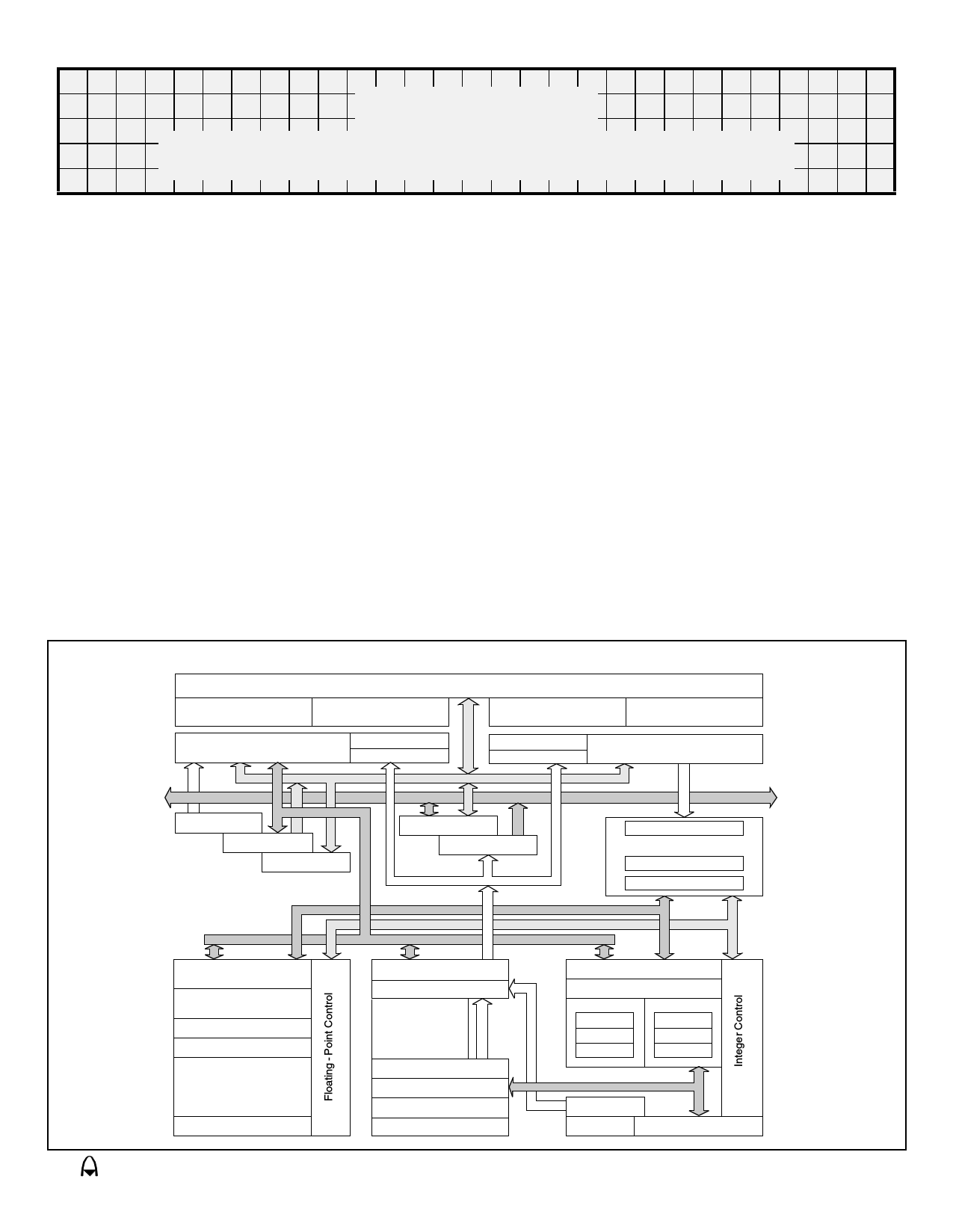
BLOCK DIAGRAM
On - Chip 256K Byte Secondary Cache, 4 - Way Set Associative
Secondary Tags
Set A
Secondary Tags
Set B
Secondary Tags
Set C
Secondary Tags
Set D
Primary Data Cache
4 - Way Set Associative
DTag
DTLB
ITag
ITLB
Primary Instruction Cache
4 - Way Set Associative
A/D Bus
Pad Bus
Store Buffer
Write Buffer
Read Buffer
D Bus
Pad Buffer
Address Buffer
F-Pipe Bus
Prefetch Buffer
Instruction Dispatch Unit
F Pipe Register
M Pipe Register
M-Pipe Bus
Floating-Point
Load / Align
Floating-Point
Register File
Packer / Unpacker
Comparator
Floating-Point
MultAdd, Add, Sub,
Cvt, Div, Sqrt
Multiplier Array
Joint TLB
Coprocessor 0
DVA
System / Memory
Control
IVA
PC Incrementer
Branch PC Adder
ITLB Virtuals
Program Counter
Load Aligner
Integer Register File
M Pipe
F Pipe
Adder
Adder
StAin/Sh
Logicals
Shifter
Logicals
FA Bus
DTLB Virtuals
PLL/Clocks
Int Mult. Div. Madd
eroflex Circuit Technology – MIPS RISC Microprocessors © SCD7000SC REV B 7/30/01
1 page 
By pipelining the multiply-accumulate function and
dynamically determining the size of the input
operands, the ACT 7000SC is able to maximize
throughput while still using an area efficient
implementation.
Floating-Point Coprocessor
The ACT 7000SC incorporates a high-performance
fully pipe-lined floating-point coprocessor which
includes a floating-point register file and autonomous
execution units for multiply/ add/convert and
divide/square root. The floating-point coprocessor is a
tightly coupled co-execution unit, decoding and
executing instructions in parallel with, and in the case
of floating-point loads and stores, in cooperation with
the M pipe of the integer unit. As described earlier, the
superscalar capabilities of the ACT 7000SC allow
floating-point computation instructions to issue
concurrently with integer instructions.
Floating-Point Unit
The ACT 7000SC floating-point execution unit
supports single and double precision arithmetic, as
specified in the IEEE Standard 754. The execution
unit is broken into a separate divide/square root unit
and a pipelined multiply/add unit. Overlap of
divide/square root and multiply/add is supported.
The ACT 7000SC maintains fully precise
floating-point exceptions while allowing both
overlapped and pipelined operations. Precise
exceptions are extremely important in object-oriented
programming environments and highly desirable for
debugging in any environment.
The floating-point unit’s operation set includes
floating-point add, subtract, multiply, multiply-add,
divide, square root, reciprocal, reciprocal square root,
conditional moves, conversion between fixed-point
and floating-point format, conversion between
floating-point formats, and floating-point compare.
Table 5 gives the latencies of the floating-point
instructions in internal processor cycles.
Floating-Point General Register File
The floating-point general register file, FGR, is
made up of thirty-two 64-bit registers. With the
floating-point load and store double instructions,
LDC1 and SDC1, the floating-point unit can take
advantage of the 64-bit wide data cache and issue a
floating-point coprocessor load or store double-word
instruction in every cycle.
The floating-point control register file contains two
registers; one for determining configuration and
revision information for the coprocessor and one for
control and status information. These registers are
primarily used for diagnostic software, exception
handling, state saving and restoring, and control of
rounding modes.
Aeroflex Circuit Technology
5
Table 5 – Floating Point Latencies and
Repeat Rates
Operation
Latency
single/double
Repeat Rate
single/double
fadd
fsub
fmult
fmadd
fmsub
fdiv
fsqrt
frecip
frsqrt
fcvt.s.d
fcvt.s.w
fcvt.s.l
fcvt.d.s
fcvt.d.w
fcvt.d.l
fcvt.w.s
fcvt.w.d
fcvt.l.s
fcvt.l.d
fcmp
fmov, fmovc
fabs, fneg
4
4
4/5
4/5
4/5
21/36
21/36
21/36
38/68
4
6
6
4
4
4
4
4
4
4
1
1
1
1
1
1/2
1/2
1/2
19/34
19/34
19/34
36/66
1
3
3
1
1
1
1
1
1
1
1
1
1
To support superscalar operations, the FGR has
four read ports and two write ports, and is fully
bypassed to minimize operation latency in the
pipeline. Three of the read ports and one write port
are used to support the combined multiply-add
instruction while the fourth read and second write port
allows a concurrent floating-point load or store and
conditional moves.
System Control Coprocessor (CP0)
The system control coprocessor (CP0) in the MIPS
architecture is responsible for the virtual memory
sub-system, the exception control system, and the
diagnostics capability of the processor. In the MIPS
architecture, the system control coprocessor (and
thus the kernel software) is implementation
dependent. For memory management, the ACT
7000SC CP0 is logically identical to that of the
RM5200 Family and R5000. For interrupt exceptions
and diagnostics, the ACT 7000SC is a superset of the
RM5200 Family and R5000 implementing additional
features described later in the sections on Interrupts,
the Test/Breakpoint facility, and the Performance
Counter facility.
The memory management unit controls the virtual
memory system page mapping. It consists of an
instruction address translation buffer, or ITLB, a data
SCD7000SC REV B 7/30/01 Plainview NY (516) 694-6700
5 Page 
Primary Write Buffer
Writes to secondary cache or external memory,
whether cache miss write-backs or stores to
uncached or write-through addresses, use the
integrated primary write buffer. The write buffer holds
up to four 64-bit address and data pairs. The entire
buffer is used for a data cache write-back and allows
the processor to proceed in parallel with memory
update. For uncached and write-through stores, the
write buffer significantly increases performance by
decoupling the SysAD bus transfers from the
instruction execution stream.
System Interface
The ACT 7000SC provides a high-performance
64-bit system interface which is compatible with the
RM5200 Family and R5000. Unlike the R4000 and
R5000 family processors which provide only an
integral multiplication factor between SysClock and
the pipeline clock, the ACT 7000SC also allows
half-integral multipliers, thereby providing greater
granularity in the designers choice of pipeline and
system interface frequencies.
The interface consists of a 64-bit Address/Data bus
with 8 check bits and a 9-bit command bus. In
addition, there are six handshake signals and six
interrupt inputs. The interface has a simple timing
specification and is capable of transferring data
between the processor and memory at a peak rate of
600 MB/sec with a 75 MHz SysClock.
Figure 6 shows a typical embedded system using
the ACT 7000SC. This example shows a system with
a bank of DRAMs, and an interface ASIC which
provides DRAM control as well as an I/O port.
System Address/Data Bus
The 64-bit System Address Data (SysAD) bus is
used to transfer addresses and data between the
ACT 7000SC and the rest of the system. It is
protected with an 8-bit parity check bus, SysADC.
The system interface is configurable to allow easy
interfacing to memory and I/O systems of varying
frequencies. The data rate and the bus frequency at
which the ACT 7000SC transmits data to the system
interface are programmable via boot time mode
control bits. Also, the rate at which the processor
receives data is fully controlled by the external device.
Therefore, either a low cost interface requiring no
read or write buffering or a faster, high-performance
interface can be designed to communicate with the
ACT 7000SC. Again, the system designer has the
flexibility to make these price/performance trade-offs.
System Command Bus
The ACT 7000SC interface has a 9-bit System
Command (SysCmd) bus. The command bus
indicates whether the SysAD bus carries an address
or data. If the SysAD bus carries an address, then the
SysCmd bus also indicates what type of transaction is
to take place (for example, a read or write). If the
SysAD bus carries data, then the SysCmd bus also
gives information about the data (for example, this is
the last data word transmitted, or the data contains an
error). The SysCmd bus is bidirectional to support
both processor requests and external requests to the
ACT 7000SC. Processor requests are initiated by the
ACT 7000SC and responded to by an external
device. External requests are issued by an external
device and require the ACT 7000SC to respond.
The ACT 7000SC supports one to eight byte and
32-byte block transfers on the SysAD bus. In the case
of a sub-double-word transfer, the 3 low-order
address bits give the byte address of the transfer, and
the SysCmd bus indicates the number of bytes being
transferred.
Handshake Signals
There are six handshake signals on the system
interface. Two of these, RdRdy* and WrRdy*, are
used by an external device to indicate to the ACT
7000SC whether it can accept a new read or write
ACT 7000SC
DRAM
72
Latch
72 SysAD Bus
72
SysCmd
25
Flash /
Boot
ROM
Address
Control
8
Memory I/O
Controller
XX
PCI Bus
Aeroflex Circuit Technology
Figure 6 – Typical Embedded System Block Diagram
11 SCD7000SC REV B 7/30/01 Plainview NY (516) 694-6700
11 Page | ||
| Páginas | Total 25 Páginas | |
| PDF Descargar | [ Datasheet ACT-7000SC-225F17C.PDF ] | |
Hoja de datos destacado
| Número de pieza | Descripción | Fabricantes |
| ACT-7000SC-225F17C | ACT 7000SC 64-Bit Superscaler Microprocessor | Aeroflex Circuit Technology |
| ACT-7000SC-225F17I | ACT 7000SC 64-Bit Superscaler Microprocessor | Aeroflex Circuit Technology |
| ACT-7000SC-225F17M | ACT 7000SC 64-Bit Superscaler Microprocessor | Aeroflex Circuit Technology |
| ACT-7000SC-225F17Q | ACT 7000SC 64-Bit Superscaler Microprocessor | Aeroflex Circuit Technology |
| Número de pieza | Descripción | Fabricantes |
| SLA6805M | High Voltage 3 phase Motor Driver IC. |
Sanken |
| SDC1742 | 12- and 14-Bit Hybrid Synchro / Resolver-to-Digital Converters. |
Analog Devices |
|
DataSheet.es es una pagina web que funciona como un repositorio de manuales o hoja de datos de muchos de los productos más populares, |
| DataSheet.es | 2020 | Privacy Policy | Contacto | Buscar |