|
|
|
PDF ADM1022 Data sheet ( Hoja de datos )
| Número de pieza | ADM1022 | |
| Descripción | Low-Cost PC Temperature Monitor and Fan Control ASIC | |
| Fabricantes | Analog Devices | |
| Logotipo | ||
Hay una vista previa y un enlace de descarga de ADM1022 (archivo pdf) en la parte inferior de esta página. Total 19 Páginas | ||
|
No Preview Available !
a
Low-Cost PC Temperature
Monitor and Fan Control ASIC
ADM1022
FEATURES
External Temperature Measurement with Remote
Diode (Two Channels)
On-Chip Temperature Sensor
Interrupt and Over-Temperature Outputs
Fault Tolerant Fan Control
Brownout Detection
LDCM Support
System Management Bus (SMBus)
Standby Mode to Minimize Power Consumption
Limit Comparison of all Monitored Values
APPLICATIONS
Network Servers and Personal Computers
Microprocessor-Based Office Equipment
Test Equipment and Measuring Instruments
GENERAL DESCRIPTION
The ADM1022 is a low cost temperature monitor and fan con-
troller for microprocessor-based systems. The temperature of
one or two remote sensor diodes may be measured, allowing
monitoring of processor temperature in single- or dual-pro-
cessor systems.
Measured values can be read out via a serial System Manage-
ment Bus, and values for limit comparisons can be programmed
in over the same serial bus.
The ADM1022 also contains a DAC for fan speed control.
Automatic hardware temperature trip points are provided and
the fan will be driven to full speed if they are exceeded.
Finally, the chip has two supply voltage monitors for brownout
detection.
The ADM1022’s 3.0 V to 5.5 V supply voltage range, low supply
current, and SMBus interface make it ideal for a wide range of
applications. These include hardware monitoring and protection
applications in personal computers, electronic test equipment
and office electronics.
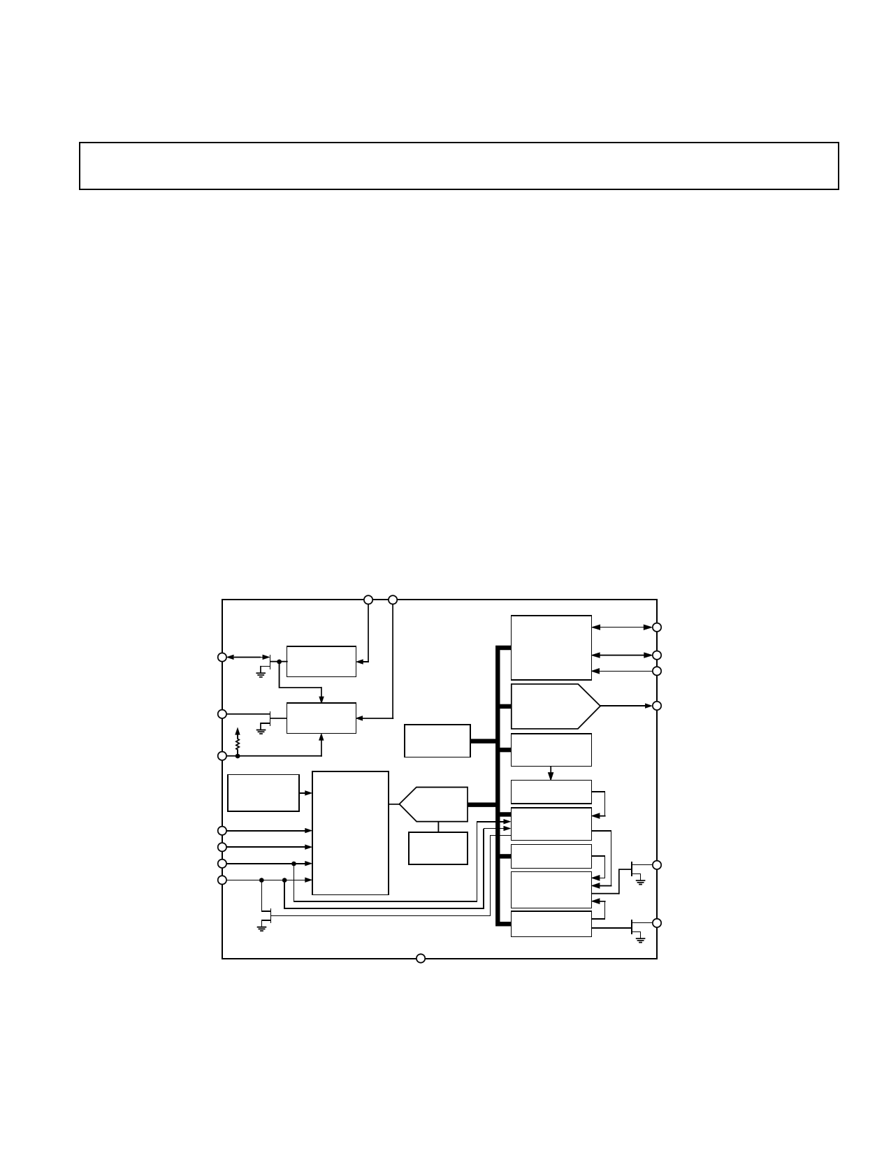
FUNCTIONAL BLOCK DIAGRAM
VCC VMON
RST1
RESET
GENERATOR 1
ADM1022
RST2
VCC
20k⍀
MR
RESET
GENERATOR 2
BANDGAP
TEMPERATURE
SENSOR
D1+
D1–
D2+/GPI
D2–/THERM
ANALOG
MULTIPLEXER
ADDRESS
POINTER
REGISTER
ADC
2.5V
BANDGAP
REFERENCE
SERIAL BUS
INTERFACE
ANALOG
OUTPUT
REGISTER
AND 8-BIT DAC
VALUE AND
LIMIT
REGISTERS
LIMIT
COMPARATORS
INTERRUPT
STATUS
REGISTERS
INT MASK
REGISTER
MASK
GATING
CONFIGURATION
REGISTER
ADD/NTEST_OUT
SDA
SCL
FAN_SPD/NTEST_IN
INT
FAN_OFF
GND
REV. 0
Information furnished by Analog Devices is believed to be accurate and
reliable. However, no responsibility is assumed by Analog Devices for its
use, nor for any infringements of patents or other rights of third parties
which may result from its use. No license is granted by implication or
otherwise under any patent or patent rights of Analog Devices.
One Technology Way, P.O. Box 9106, Norwood, MA 02062-9106, U.S.A.
Tel: 781/329-4700 World Wide Web Site: http://www.analog.com
Fax: 781/326-8703
© Analog Devices, Inc., 2000
1 page 
ADM1022
Pin
No. Mnemonic
1 FAN_OFF
2 MR
3 RST1
4 GND
5 VCC
6 VMON
7 RST2
8 FAN_SPD/NTEST_IN
9 D1–
10 D1+
11 D2–/THERM
12 D2+/GPI
13 ADD/NTEST_OUT
14 INT
15 SCL
16 SDA
PIN FUNCTION DESCRIPTION
Description
Digital Output (Open-Drain) Fan Off Request. When asserted low this indicates a request to shut
off the fan independent of the FAN_SPD output. When negated (output FET off) it indicates that
the fan may be turned on.
Digital Input, Manual Reset. A logic low on this input causes RST2 to be asserted. Once this input
is negated that output will remain asserted for tRP. This input has an internal 20 kΩ pull-up resistor.
Leave unconnected if not used.
Digital I/O (Open-Drain). This pin is asserted low while VCC remains below the reset threshold. It
remains asserted for tRP after the reset condition is terminated. It is bidirectional so the ADM1022 can
be optionally reset; external logic must be used to prevent system auxiliary reset from occurring
when used as an input.
GROUND. Power and Signal Ground.
POWER 3.3 V. Power source and voltage monitor input for first reset generator.
Analog Input. Voltage monitor input for second reset generator.
Digital Output (Open-Drain). This pin is asserted low under any of the following conditions:
– VMON or VCC remains below the reset threshold
– while MR is held low
– while RST1 is asserted.
It remains asserted for tRP after the reset conditions are terminated.
Analog Output/Test Input. An active-high input that enables NAND board-level connectivity testing.
Refer to section on NAND testing. Used as an analog output for fan speed control when NAND
test is not selected.
Remote Thermal Diode Negative Input. This is the negative input (current sink) from the remote
thermal diode. This also serves as the negative input into the A/D.
Remote Thermal Diode Positive Input. This is the positive input (current source) from the remote
thermal diode. This serves as the positive input into the A/D.
Analog Input/Digital I/O (Open-Drain). Can be programmed as negative input for a second diode
temperature sensor, or as a digital I/O pin. In this case it is an active low thermal overload output
that indicates a violation of a temperature set point (over-temperature). Also acts as an input to
provide external fan control. When this pin is pulled low by an external signal, a status bit is set and
the fan speed is set to full on.
Analog/Digital Input. Can be programmed as the positive input for a second diode sensor, or as a
general-purpose logic input. In this case it can be programmed as an active high or active low input
that sets Bit 4 of the Status Registers. This bit can only be reset by reading the status registers, pro-
vided GPI is in the inactive state.
Digital I/O. The lowest order programmable bit of the SMBus Address. ADD is sampled at power-
up and changing it while powered on will have no immediate effect. This pin also functions as an
output when doing a NAND test.
Digital Output (Open Drain), System Interrupt Output. This signal indicates a violation of a set
trip point. The output is enabled when Bit 1 of the Configuration Register is set to 1. The default
state is disabled.
Digital Input SMBus Clock.
Digital I/O (Open-Drain) SMBus Bidirectional Data.
REV. 0
–5–
5 Page 
ANALOG OUTPUT
The ADM1022 has a single analog output (FAN_SPD) from an
unsigned 8-bit DAC that produces 0 V–2.5 V. The analog out-
put register defaults to 00 during power-on reset, which produces
minimum fan speed. The analog output may be amplified and
buffered with external circuitry such as an op amp and transistor
to provide fan speed control.
Suitable fan drive circuits are given in Figures 14a to 14e. When
using any of these circuits, the following points should be noted:
1. All of these circuits will provide an output range from zero to
almost +VFAN.
2. To amplify the 2.5 V range of the analog output up to +VFAN,
the gain of these circuits needs to be set as shown.
3. Care must be taken when choosing the op amp to ensure that
its input common-mode range and output voltage swing are
suitable.
4. The op amp may be powered from the +V rail alone. If it
is powered from +V then the input common-mode range
should include ground to accommodate the minimum output
voltage of the DAC, and the output voltage should swing below
0.6 V to ensure that the transistor can be turned fully off.
5. In all these circuits, the output transistor must have an ICMAX
greater than the maximum fan current, and be capable of dis-
sipating power due to the voltage dropped across it when the
fan is not operating at full speed.
6. If the fan motor produces a large back ElectroMotive Force
(EMF) when switched off, it may be necessary to add clamp
diodes to protect the output transistors in the event that the
output goes from full-scale to zero very quickly.
7. Pulling FAN_SPD/NTEST_IN high externally on power-up
causes NAND Test Mode to be invoked on the ADM1022.
Therefore, a 4.7 kΩ pull-down resistor should be added
externally to the FAN_SPD pin to prevent ADM1022 inad-
vertently entering the NAND Tree Test Mode.
Figure 14c shows how the FAN_OFF signal may be used (with
any of the control circuits) to gate the fan on and off indepen-
dent of the value on the FAN_SPD/NTEST_IN pin.
5V
FAN_SPD
AD8541
+
R1
10k⍀
R2
15k⍀
Q1
NDT452 P
5V
FAN
Figure 14a. 5 V Fan Circuit with Op Amp
FAN_SPD
ADM1022
12V
AD8519
+
R4
1k⍀
R3
1k⍀
R1
10k⍀
R2
39k⍀
Q1
BD136
2SA968
Figure 14b. 12 V Fan Circuit with Op Amp and PNP
Transistor
12V
FAN_SPD
AD8519
+
R3
100k⍀
R2
39k⍀
3.3V
R1
10k⍀
R4
1k⍀
FAN_OFF
Q1
NDT452 P
Q2
NDT3055L
Figure 14c. 12 V Fan Circuit with Op Amp and P-Channel
MOSFET
12V
R3
100k⍀
R4
100k⍀
Q3
NDT452 P
FAN_SPD
R5
5k⍀
Q1/Q2
MBT3904
DUAL
R2
3.9k⍀
R1
1k⍀
Figure 14d. Discrete 12 V Fan Drive Circuit with
P-Channel MOSFET, Single Supply
12V
R5
100k⍀
R4
100k⍀
Q3
BC556
2N3906
FAN_SPD
R6
5k⍀
Q1/Q2
MBT3904
DUAL
R3
100⍀
R2
3.9k⍀
R1
1k⍀
Q4
BD132
TIP32A
Figure 14e. Discrete 12 V Fan Drive Circuit with Bipolar
Output Single Supply
REV. 0
–11–
11 Page | ||
| Páginas | Total 19 Páginas | |
| PDF Descargar | [ Datasheet ADM1022.PDF ] | |
Hoja de datos destacado
| Número de pieza | Descripción | Fabricantes |
| ADM1020 | 8-Lead/ Low-Cost/ System Temperature Monitor | Analog Devices |
| ADM1021 | Low Cost Microprocessor System Temperature Monitor | Analog Devices |
| ADM1021A | Low Cost Microprocessor System Temperature Monitor Microcomputer | ON Semiconductor |
| ADM1021A | System Temperature Monitor Microcomputer | Analog Devices |
| Número de pieza | Descripción | Fabricantes |
| SLA6805M | High Voltage 3 phase Motor Driver IC. |
Sanken |
| SDC1742 | 12- and 14-Bit Hybrid Synchro / Resolver-to-Digital Converters. |
Analog Devices |
|
DataSheet.es es una pagina web que funciona como un repositorio de manuales o hoja de datos de muchos de los productos más populares, |
| DataSheet.es | 2020 | Privacy Policy | Contacto | Buscar |